Bi-directional DC to DC power converter having a neutral terminal

a power converter and neutral terminal technology, applied in the direction of electric variable regulation, process and machine control, instruments, etc., can solve the problem of no voltage buck function

Active Publication Date: 2012-03-06
ABLEREX ELECTRONICS CO LTD
View PDF7 Cites 24 Cited by
  • Summary
  • Abstract
  • Description
  • Claims
  • Application Information

AI Technical Summary

Problems solved by technology

However, the conventional boost power converter has no voltage buck function and only permits the electric energy to be transmitted in one direction.

Method used


Image

  • Bi-directional DC to DC power converter having a neutral terminal
  • Bi-directional DC to DC power converter having a neutral terminal
  • Bi-directional DC to DC power converter having a neutral terminal

Examples


Embodiment Construction

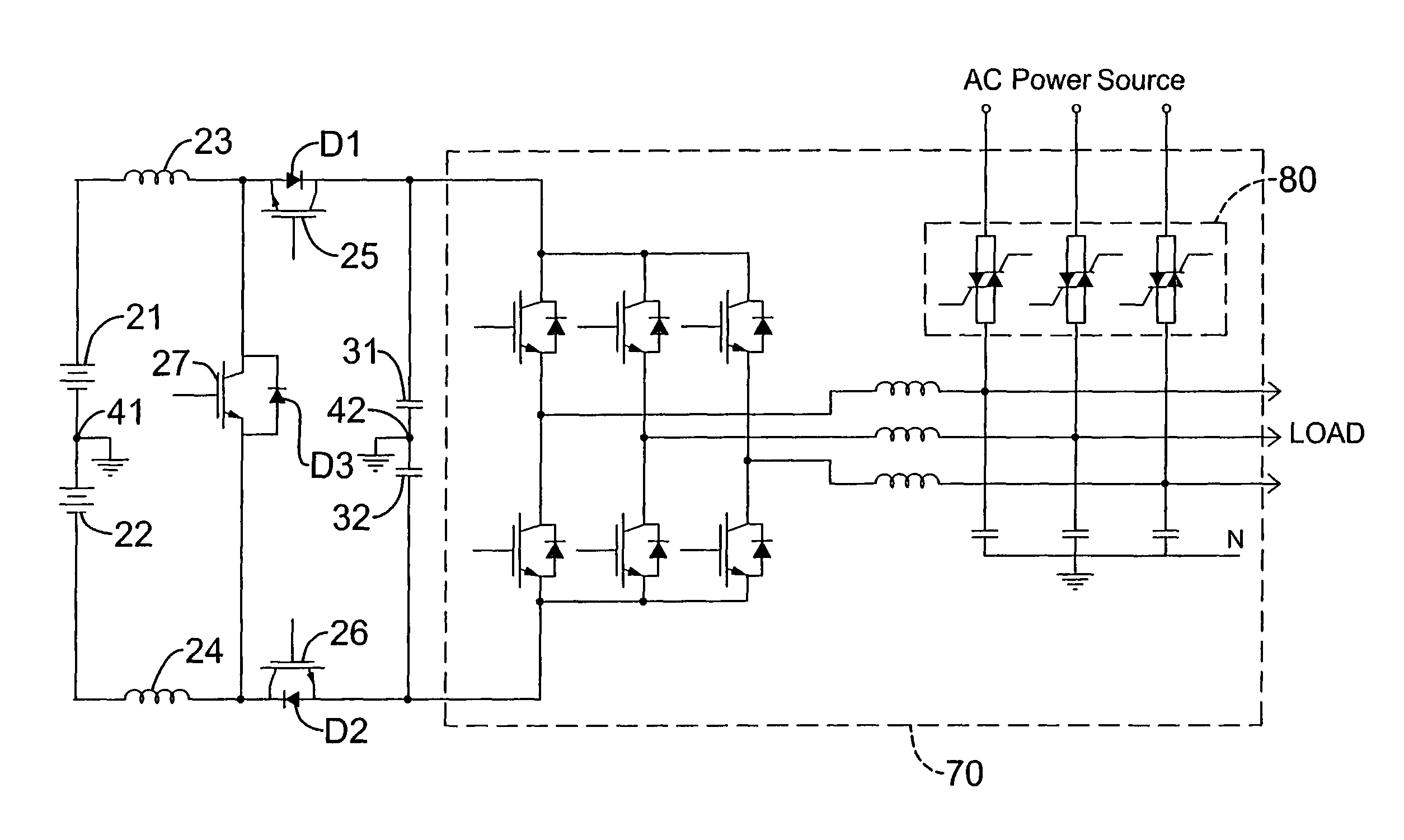
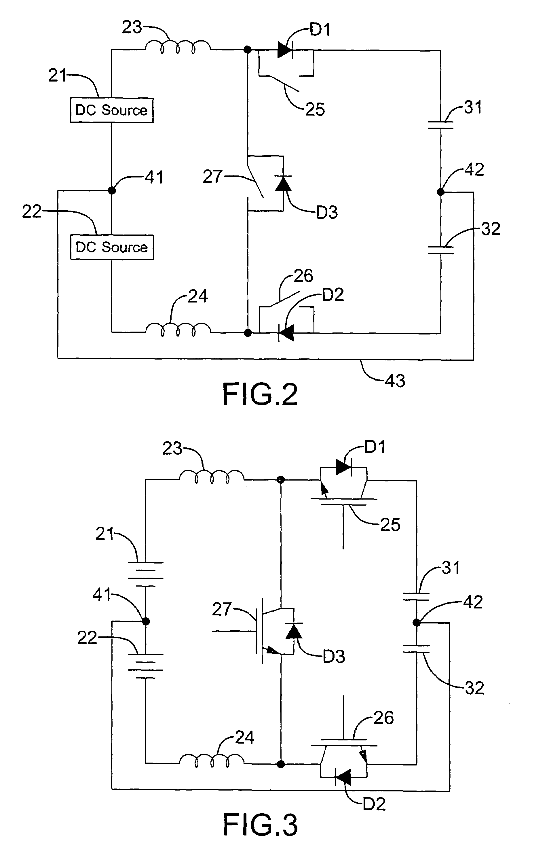
[0026]With reference to FIG. 2, a bi-directional DC to DC power converter having a neutral terminal in accordance with the present invention is illustrated. The bi-directional DC to DC power converter comprises a first DC power circuit, a second DC power circuit and a third switch (27) connected between the first and the second DC power circuits.

[0027]The first DC power circuit comprises a first DC source (21), a first inductor (23), a first switch (25) and a first capacitor (31) being connected sequentially. The first DC source (21) has a positive terminal and a negative terminal. The first inductor (23) has two terminals respectively connected to the positive terminal of the first DC source (21) and the first switch (25). The first switch (25) is controlled to selectively turn on or off and further connected reversely with a first diode (D1) in parallel.

[0028]The second DC power circuit comprises a second DC source (22), a second inductor (24), a second switch (26) and a second ca...


PUM


Abstract

A bi-directional DC to DC power converter includes two DC sources, two inductors respectively connected to the two DC sources, a first switch and a second switch respectively connected to the two inductors, two capacitors respectively connected to the two switches, and a third switch connected between the two inductors. The first, second and third switches are respectively connected reversely with a diode in parallel. When the third switch is alternately turned on and off and the first and second switches are always turned off, the power converter operates as a boost power converter and electric energy flows from the two DC sources to the two capacitors. When the third switch is always turned off and the first and second switches are synchronously turned on or off, the power converter operates as a buck power converter and electric energy flows from the two capacitors to the two DC sources.

Description

BACKGROUND OF THE INVENTION[0001]1. Field of the Invention[0002]The present invention is related to a bi-directional DC to DC power converter having a neutral terminal. More particularly, the bi-directional DC to DC power converter having the neutral terminal can be operated in a boost mode or a buck mode to allow a bi-directional electric energy transmission.[0003]2. Description of Related Art[0004]A DC to DC boost / buck power converter with a neutral terminal is often used in power related apparatus. Taking the uninterruptible power supply (UPS) system as an example, a DC to DC boost power converter with a neutral terminal is used to step up an input DC voltage having a neutral terminal to produce an output DC voltage having a neutral terminal with a required level. The output DC voltage having a neutral terminal can be applied to other subsequent devices.[0005]With reference to FIG. 1, U.S. Pat. No. 6,154,380 discloses a conventional boost power converter being composed of an AC p...

Claims


Application Information

Patent Timeline
Patent Type & Authority Patents(United States)
IPC IPC(8): H02M7/5387G05F1/577H02M3/156
CPCH02M3/1582H02M3/1584
Inventor LEE, YI-HUHSU, WENWU, CHIN-CHANGCHOU, HUNG-LIANGFENG, YA-TSUNG
Owner ABLEREX ELECTRONICS CO LTD
Why Eureka
Try Eureka