
Apparatus and method of displaying the three-dimensional image

a three-dimensional image and display apparatus technology, applied in the field of three-dimensional image display apparatus and a three-dimensional image display method, can solve the problems of reducing the resolution of the three-dimensional image, increasing the lens pitch, and incomplete movement parallaxes

Inactive Publication Date: 2012-04-10
KK TOSHIBA
View PDF11 Cites 7 Cited by
  • Summary
  • Abstract
  • Description
  • Claims
  • Application Information

AI Technical Summary

Problems solved by technology

However, with the resolution of LCD fixed, lens pitch increases to reduce the resolution of the three-dimensional image.
With the multi-lens scheme, importance is attached to the definition of the eye point image, resulting in incomplete movement parallaxes.
A problem with the display apparatus disclosed in JP-A 2004-212666 (KOKAI) is an increase in the number of directions in which parallax images are acquired.
Also for live action, the increase in the number of directions in which multi-eye-point images may disadvantageously increase the amount of image pickup loads.
However, with this method, strictly speaking, the direction of each beam does not match the corresponding parallax information, unavoidably degrading image quality.
In general, whether the lenses or slits are arranged in front of the display panel, it is difficult to limit the number of pixels observed by the observer via one exit pupil, that is, the number of pieces of parallax information, to one, in connection with the curvature of an image surface or the aperture.
That is, disadvantageously, the observer may actually view at least two pixels via the one exit pupil.
Another problem is that an image exceeding a protrusion or depth limit as defined in H. Hoshino, F. Okano, H. Isono, and I. Yuyama, J. Opt. Soc. Am. A., Vol. 15, pp.
This problem occurs because the intervals (angles) at which parallax information is presented needs to be reduced in order to display a three-dimensional image with a significant protrusion or depth but because the intervals (angles) are insufficient.
As described above, the method for displaying three-dimensional images utilizing multiple parallaxes on the basis of the II scheme disadvantageously imposes the heavy burden of creating two-dimensional images to be displayed on the display panel.
The three-dimensional image display apparatus offering multiple parallaxes so as to enable three-dimensional viewing with the naked eye disadvantageously makes an image appear multiplied when the image is displayed with the protrusion or depth display limit exceeded.

Method used

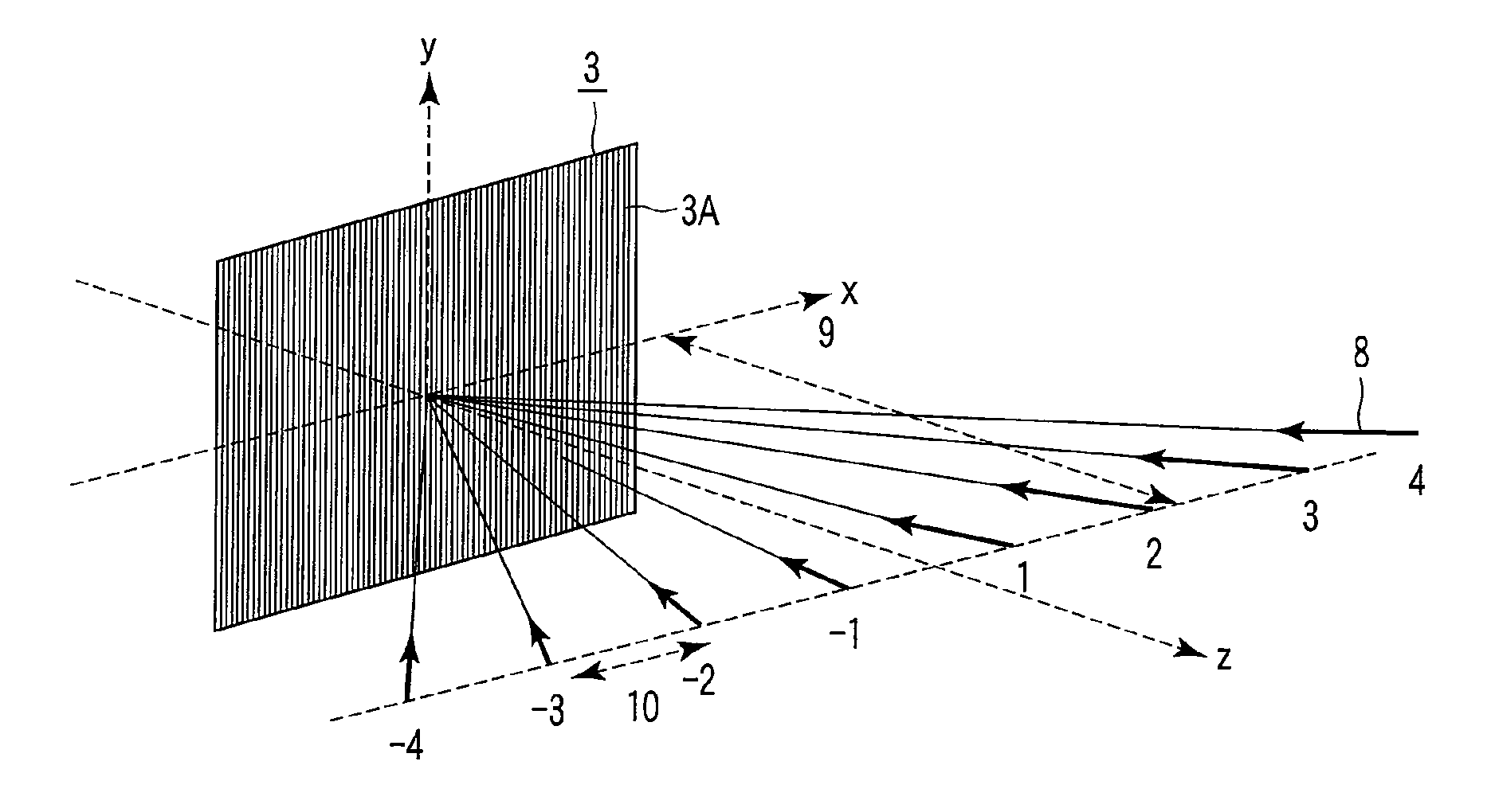
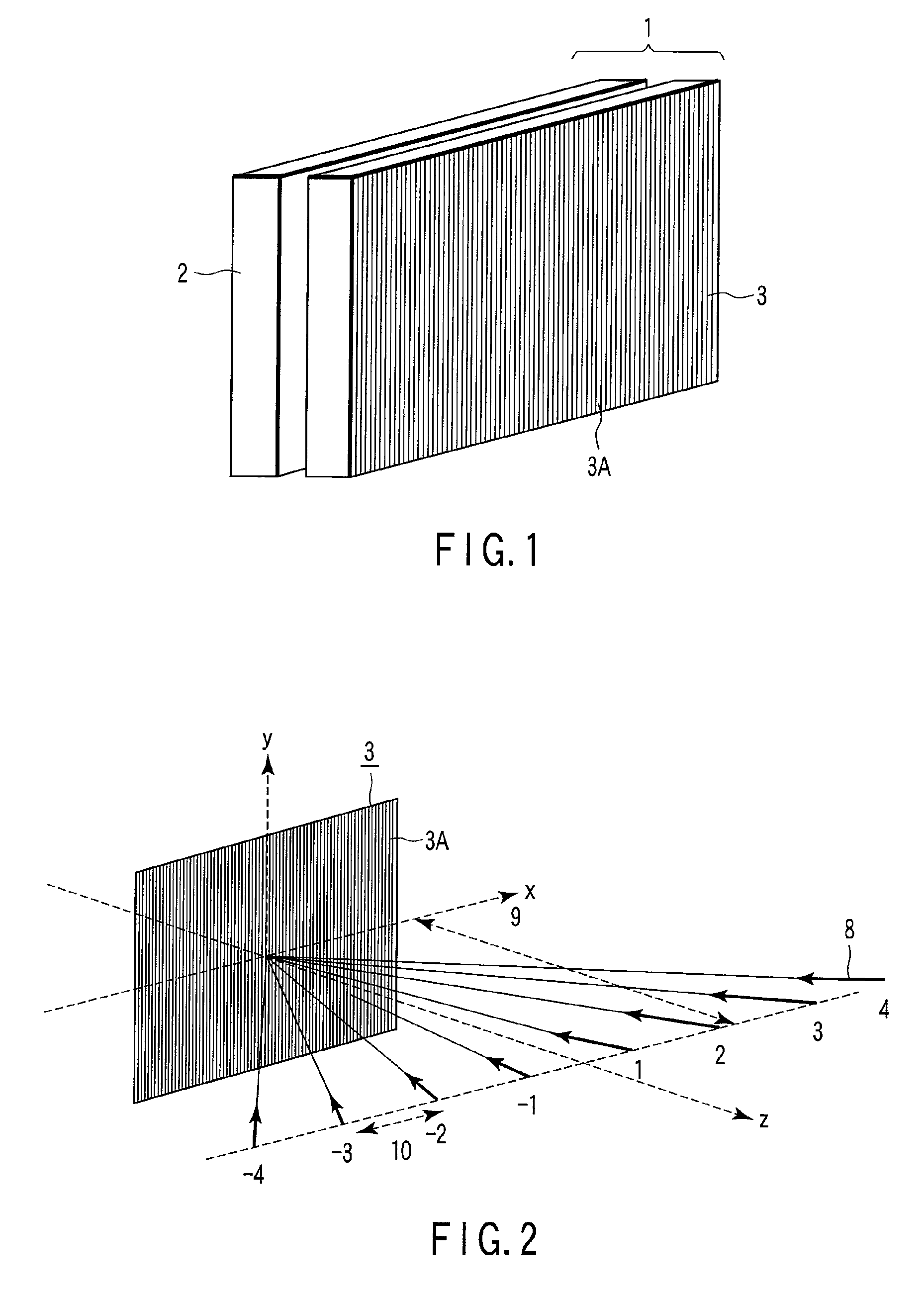
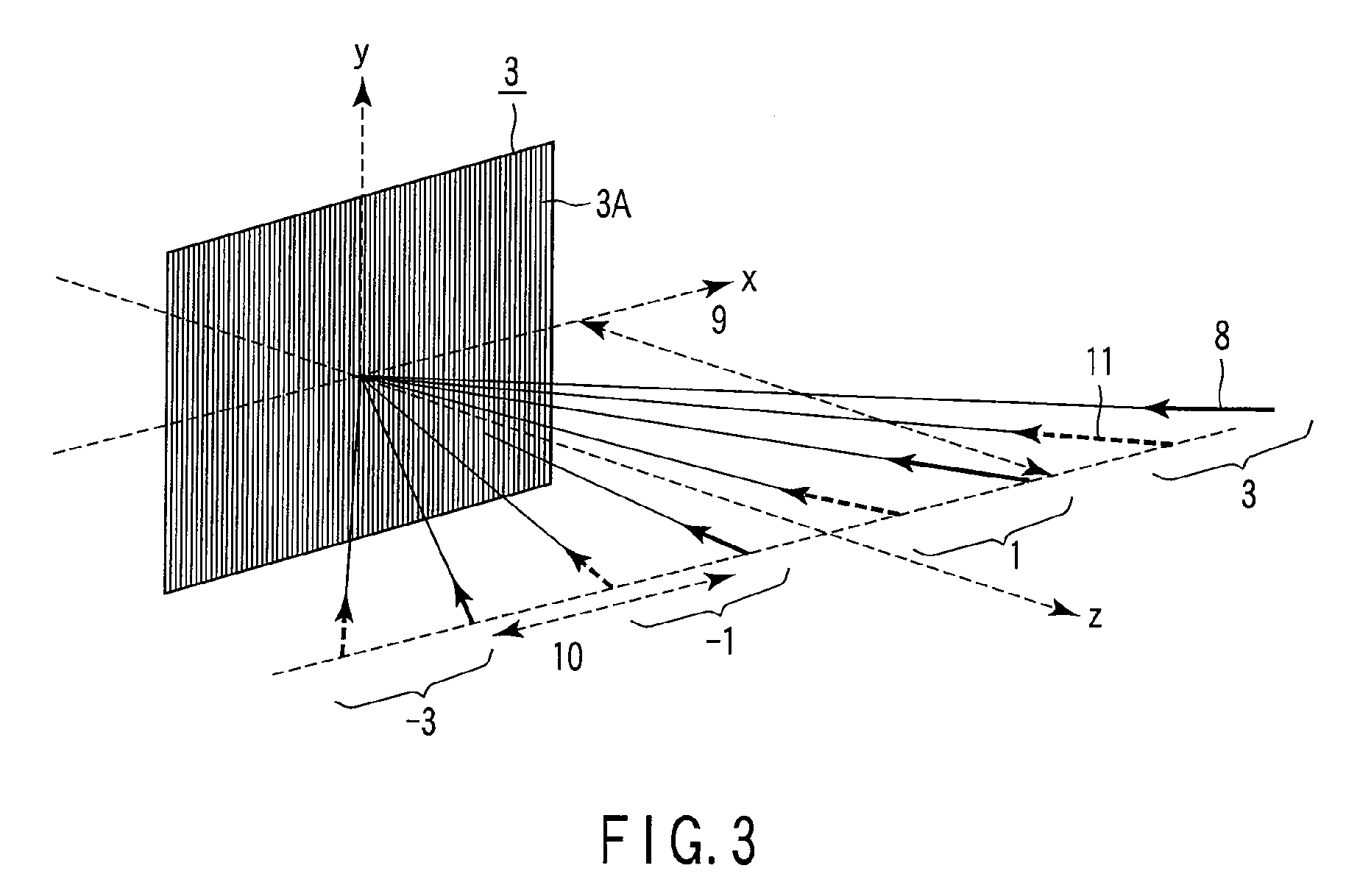

Image

  • Apparatus and method of displaying the three-dimensional image
  • Apparatus and method of displaying the three-dimensional image
  • Apparatus and method of displaying the three-dimensional image

Examples


embodiment 1 (

the vertical lens in accordance with the 1D-II Scheme Depending on the Display Position)

[0115]Description will be given of a case in which PT=0 (vertical lens 3A) and the number of parallaxes is 12. The observation distance was set at 700 mm. Even with the 12 parallaxes, the number of multi-lens cameras required to provide one screen is 22 in order to maximize the viewing area width at the observation distance of 700 mm. Detailed descriptions are omitted here. With this three-dimensional image display apparatus, when the spatial frequency of the model to be displayed is 320 cpr, the front display limit (Dn) and the rear display limit (Df) are only 23.7 mm and 25.4 mm, respectively. It has been found that with this three-dimensional image display apparatus, 2 sub-pixels (C=2) are observed, on average, via one lens 3A at the viewing distance. In this case, the amount of cross talk (C′) on the screen is 3 as shown in FIG. 4C. For those of the models displayed on the three-dimensional i...

embodiment 2

[0117]A three-dimensional image display apparatus in Embodiment 2 was the same as that in Embodiment 1 except that the cross talk amount C was 1. Possible multiplication was successfully prevented on the basis of the following determinative equation.

z_m>Dn or z_m

embodiment 3 (

the oblique lens in accordance with the 1D-II scheme depending on the rendering speed)

[0118]Description will be given of a case in which PT=4 (vertical lens 3A) and the number of parallaxes was 16. The observation distance was set at 700 mm. Even with the 16 parallaxes, the number of multi-lens cameras required to provide one screen is 30 in order to maximize the viewing area width at the observation distance of 700 mm. Detailed descriptions are omitted here. The three-dimensional image display apparatus was used to perform real-time rendering so as to change the display in response to the observer's operation. Every time CG models created using a DirectX base are manipulated, the 30 cameras generate respective multi-eye-point images. Appropriate software then executes a rearranging process on the images in sub-pixel units to generate element images. The element images are displayed on the two-dimensional image display device to allow a three-dimensional image to be viewed via the l...


PUM


Abstract

A three-dimensional image display apparatus displays element images each composed of a set of parallax component images. An exit pupil array is located opposite the display surface. Exit pupils of the array correspond to the respective element images. The horizontal pitch of the exit pupils or an integral multiple of the horizontal pitch is set equal or slightly smaller than an integral multiple of the horizontal pitch of pixels. The parallax component images are oriented in different directions via the exit pupil. Principal beams from the parallax component images via the exit pupils are emitted substantially parallel to one another. The element image contains substantially the same parallax image component in two pixel areas in which two adjacent parallax image components are otherwise displayed. The same parallax image component is oriented in different directions via the corresponding exit pupil.

Description

CROSS-REFERENCE TO RELATED APPLICATIONS[0001]This application is based upon and claims the benefit of priority from prior Japanese Patent Application No. 2007-087864, filed Mar. 29, 2007, the entire contents of which are incorporated herein by reference.BACKGROUND OF THE INVENTION[0002]1. Field of the Invention[0003]The present invention relates to a three-dimensional image display apparatus and a method for displaying a three-dimensional image.[0004]2. Description of the Related Art[0005]In recent years, apparatuses have been developed which display three-dimensional images that can be observed with the naked eye. Naked-eye display apparatuses for three-dimensional images are known to be based on a twin lens scheme or a multi-lens scheme. In the twin lens or multi-lens three-dimensional image display apparatus, a beam control element such as a lenticular sheet (a flat protruding rod and lens array having lens properties only in a horizontal direction) or a parallax barrier is arran...

Claims


Application Information

Patent Timeline
Patent Type & Authority Patents(United States)
IPC IPC(8): H04N13/04G02B30/27G02B30/30
CPCG02B27/2214H04N13/0404G02F1/133526H04N13/305G02B30/27G02B30/30
Inventor FUKUSHIMA, RIEKOSAISHU, TATSUOHIRAYAMA, YUZO
Owner KK TOSHIBA
Learn More