Exterior aircraft vision system using a helmet-mounted display

a technology for aircraft and display, applied in the field of external aircraft vision systems, can solve the problems of reducing the reliability and mean time between failures (mtbf) of the system, affecting the navigation of aircraft, and disorienting the turret of the aircraft,

Inactive Publication Date: 2007-02-20
THE BOEING CO
View PDF21 Cites 158 Cited by
  • Summary
  • Abstract
  • Description
  • Claims
  • Application Information

AI Technical Summary

Problems solved by technology

Unfortunately, such a FLIR turret can be disorienting because the sensor is not always pointed in the same direction as the viewer's gaze.
Furthermore, the turret and associated ball-mechanism extend outward from the skin of the aircraft, and thus presents a source of aerodynamic drag.
Moreover, the various moving parts of the turret reduce the reliability and Mean Time Between Failures (MTBF) of the system.
In contrast to infrared sensors, which respond to thermal differentials, night vision goggles can only see objects that radiate at least a minimum of light energy to the goggles, and thus cannot “see” through dense cloud cover, for example.
Night vision goggles have a relatively limited field of view, so-called “tunnel vision,” that requires aggressive scanning for situational awareness and spatial orientation, thus increasing the workload and physical fatigue of the pilot or navigator.
Additionally, large or intense light sources may tend to cause night vision goggles to “bloom” such that the image is blurred.

Method used


Image

  • Exterior aircraft vision system using a helmet-mounted display
  • Exterior aircraft vision system using a helmet-mounted display
  • Exterior aircraft vision system using a helmet-mounted display

Examples


Embodiment Construction

[0023]The present invention provides an enhanced vision system for use in vehicles, in particular aircraft, that increases the safety margin during operations of low visibility. The present system enhances situational awareness and thus increases the margin of safety during reduced visibility and / or low level flight operations, such as take-off / landing, taxiing, approaches, drop zone identification, Short Austere Air Field (SAAF) operations, etc. Although the invention is particularly useful in aircraft, other vehicles that may benefit from system include trucks and automobiles, military vehicles such as tanks, firefighting vehicles, boats and ships, submarines, etc. therefore, it should be understood that the various features of the system may be, with some modification if necessary, transferred from the aircraft environment to other vehicles.

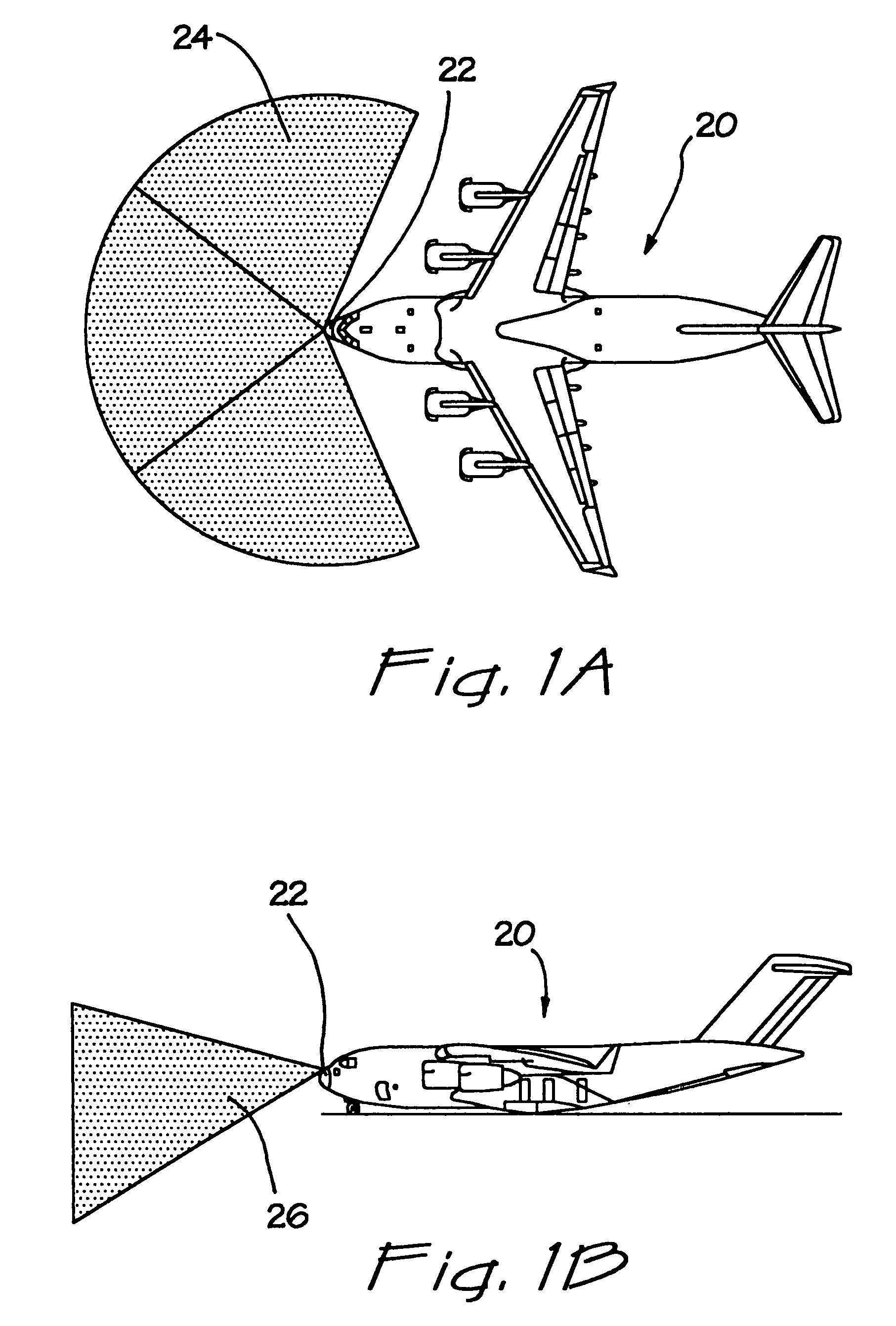
[0024]Additionally, the present enhanced vision system relies on a plurality of fixed or “staring” sensors of various kinds. A particularly u...


PUM


Abstract

An improved multiple-sensor vision system for use on vehicles or aircraft. The system utilizes a plurality of fixed sensors, such as infrared sensors, that provide signals that are recorded on tape and / or stored in memory. A processor digitally samples the stored images and provides output to a helmet-mounted display. Desirably, the sensors are arrayed in series such that their images may be juxtaposed and blended to provide a wider field-of-view image. A tracking system desirably monitors the head position of the operator, which position is then used to select various images from the processor. In this way, the operator can select various views by simply looking in that direction. In one embodiment, the array of sensors is forward-looking and positioned close to the head position of the operator to minimize parallax issues. In addition to forward-looking sensors, other sensors mounted around the vehicle / aircraft may provide rearward, hemispherical, or complete spherical coverage. Sensors that monitor the status of various instruments on board the vehicle can also provide input to the helmet-mounted display, including a moving map tile that is displayed below or to the side of the main image.

Description

RELATED APPLICATION[0001]The present invention claims the benefit of priority under 35 U.S.C. §119(e) of Provisional Application No. 60 / 141,922, filed Jun. 30, 1999.FIELD OF THE INVENTION[0002]The present invention pertains to a system for enhancing the exterior vision from an aircraft and, more particularly, to a system of a plurality of sensors that provide signals to a helmet-mounted display and enhance the situational awareness of a pilot in low visibility environments.BACKGROUND OF THE INVENTION[0003]Various systems for enhancing the vision of pilots in low visibility environments are available. Such environments include operations at nighttime, during periods of low cloud cover, in stormy weather, through smoke clouds, or combinations of the above and the like.[0004]One current system in use on the C-130 and C-141 military aircraft is a turret-mounted Forward-Looking Infrared (FLIR) sensor typically mounted to the underside of the front of the aircraft. This system requires a ...

Claims


Application Information

Patent Timeline
Patent Type & Authority Patents(United States)
IPC IPC(8): G09G5/00
CPCG01S19/15G02B27/017H04N7/181H04N5/23238G01S5/163G02B2027/014G02B2027/0187G02B2027/0138H04N23/698
Inventor GUELL, JEFF J.SCHROEDER, STEVE E.LEITCH, RODERICKMARSTAD, NORMANDEVOGEL, MICHAEL
Owner THE BOEING CO
Why Eureka
Try Eureka