Method and system for aligning a line scan camera with a lidar scanner for real time data fusion in three dimensions

a technology of line scan camera and lidar scanner, applied in surveying and navigation, measurement devices, electromagnetic wave reradiation, etc., can solve the problems of processing overhead, pixels in image data may not be attached to lidar point data with any great degree of accuracy, and it is difficult to align the line scan camera and the lidar sensor

Inactive Publication Date: 2010-06-24
AMBERCORE SOFTWARE
View PDF4 Cites 174 Cited by
  • Summary
  • Abstract
  • Description
  • Claims
  • Application Information

AI Technical Summary

Problems solved by technology

Another challenge is the accurate bore sighting and calibration of the imaging device with the LiDAR.
A third challenge is the processing overhead encountered when traditional conventional photogrammetric calculations are used to collocate the image data with the LiDAR coordinate points.
The problem with this approach is that while the imagery is collected as a frame at some point in time, the LiDAR data is collected as a

Method used


Image

  • Method and system for aligning a line scan camera with a lidar scanner for real time data fusion in three dimensions
  • Method and system for aligning a line scan camera with a lidar scanner for real time data fusion in three dimensions
  • Method and system for aligning a line scan camera with a lidar scanner for real time data fusion in three dimensions

Examples


Embodiment Construction

[0018]Embodiments are described below, by way of example only, with reference to FIGS. 1-6.

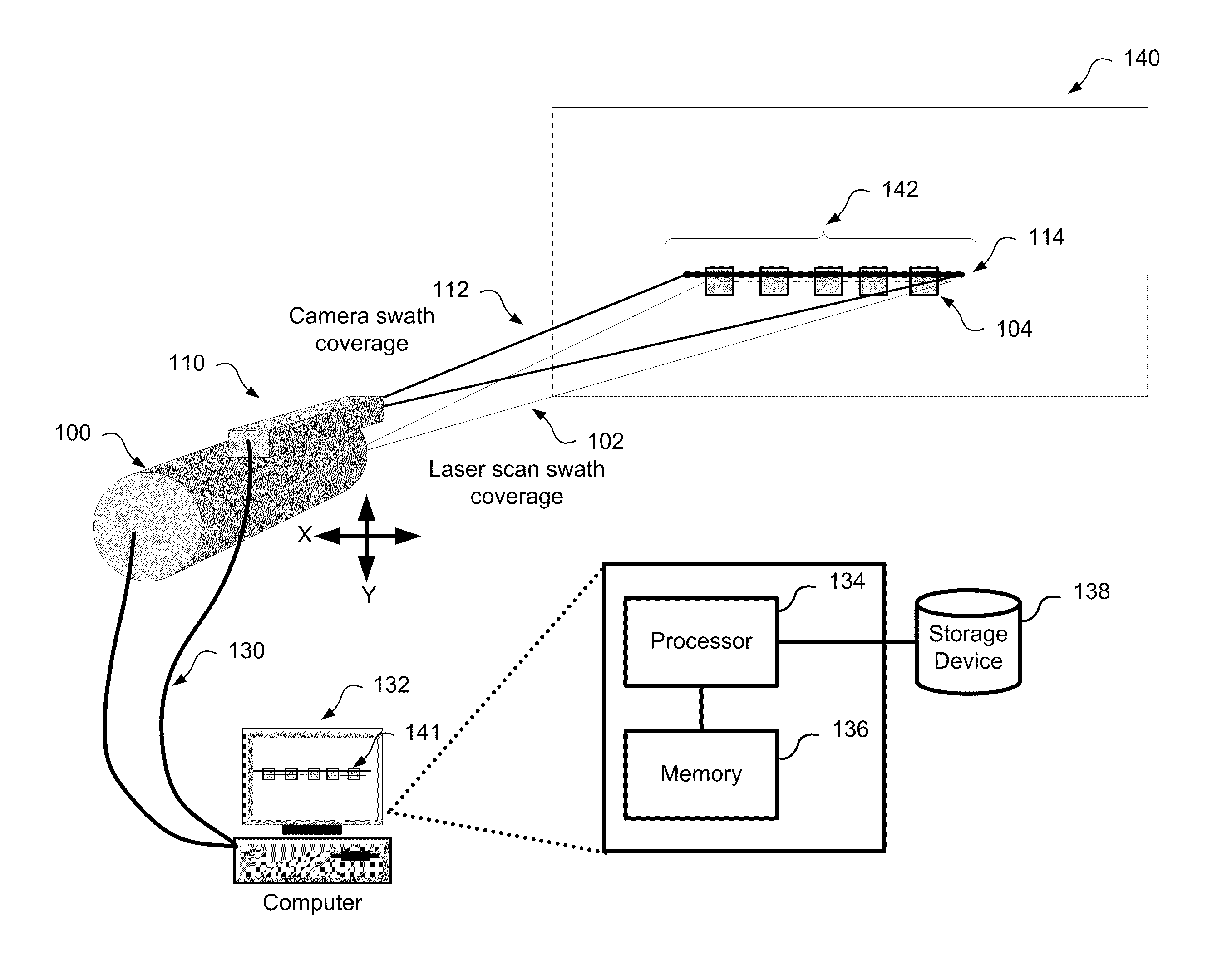
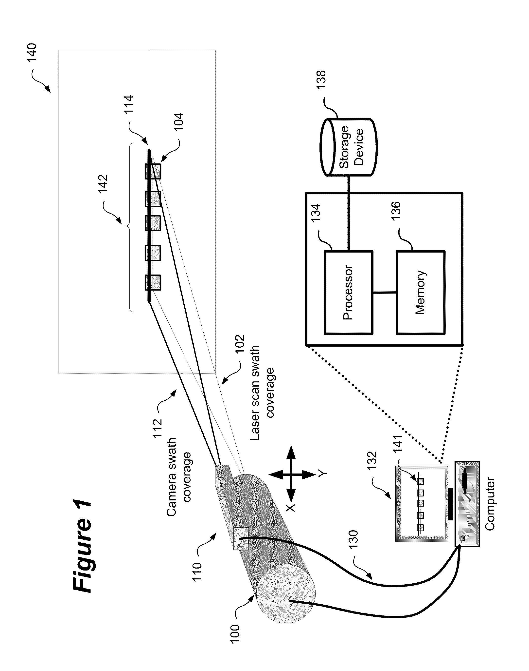
[0019]A method and system for aligning a line scan camera with a LiDAR scanner for real time data fusion in three dimensions is provided. This approach is also relevant for using an array of line scan cameras for fusion with one or more laser scanners. In order to correct for distortion between the line scan camera and LiDAR scanner correction parameters must be accurately applied to corrected data. The determination of these parameters must be performed during a calibration process to characterize the error generated by the mounting of the line scan camera and the LiDAR scanner.

[0020]FIG. 1 shows a schematic representation of a system for aligning a line scan camera with a LiDAR scanner for real time data fusion in 3-dimensions. In a LiDAR scanning system that enables the 3-D fusion of imagery the mounting of a line scan camera 110, with the LiDAR scanner 100 is critical in order to ensure ac...


PUM


Abstract

An apparatus and method for aligning a line scan camera with a Light Detection and Ranging (LiDAR) scanner for real-time data fusion in three dimensions is provided. Imaging data is captured at a computer processor simultaneously from the line scan camera and the laser scanner from target object providing scanning targets defined in an imaging plane perpendicular to focal axes of the line scan camera and the LiDAR scanner. X-axis and Y-axis pixel locations of a centroid of each of the targets from captured imaging data is extracted. LiDAR return intensity versus scan angle is determined and scan angle locations of intensity peaks which correspond to individual targets is determined. Two axis parallax correction parameters are determined by applying a least squares. The correction parameters are provided to post processing software to correct for alignment differences between the imaging camera and LiDAR scanner for real-time colorization for acquired LiDAR data.

Description

CROSS REFERENCE TO RELATED APPLICATIONS[0001]This application claims priority from U.S. Provisional Application No. 61 / 139,015 filed on Dec. 19, 2008, the contents of which is hereby incorporated by reference.TECHNICAL FIELD[0002]The present disclosure relates to the field of surveying and mapping. In particular, to a method for aligning a line scan camera with a LiDAR scanner for real time data fusion in three dimensions.BACKGROUND[0003]LiDAR (Light Detection and Ranging) is used to generate a coordinate point cloud consisting of three dimensional coordinates. Usually each point in the point cloud includes the attribute of intensity, which is a measure of the level of reflectance at the coordinate point. Intensity is useful both when extracting information from the point cloud and for visualizing the cloud.[0004]Photographic image information is another attribute that, like intensity, enhances the value of coordinate point data in the point cloud. In attaching an image attribute su...

Claims


Application Information

Patent Timeline
IPC IPC(8): G01C3/08
CPCG01S17/89G01S7/4972
Inventor KUSEVIC, KRESIMIRMRSTIK, PAULGLENNIE, CRAIG LEN
Owner AMBERCORE SOFTWARE
Why Eureka
Try Eureka