System and method for vehicle navigation using lateral offsets

a technology of lateral offset and vehicle navigation, applied in the field of digital maps, geographical positioning systems, vehicle navigation, can solve the problems of system with inertial sensors accumulating errors, prone to small amount of positional errors, and prone to accumulating small errors, etc., to achieve enhanced driver assistance operations, easy computation, and enhanced driver assistance features

Active Publication Date: 2012-10-25
TOMTOM POLSKA
View PDF8 Cites 138 Cited by
  • Summary
  • Abstract
  • Description
  • Claims
  • Application Information

AI Technical Summary

Benefits of technology

[0034]A method for vehicle navigation according to this invention uses the vehicle's lateral offset from a common reference axis to provide enhanced driver assistance features. The method comprises steps of: providing a digital map database configured to store the absolute geographic location and relative spatial location for a plurality of objects, at least two of which comprise a longitudinally extending roadway and a marker from reality disposed adjacent to the roadway. A reference axis is associated with the roadway in the digital map database. The reference axis extends generally parallel with the roadway. As the roadway curves, the axis curves with it. An object offset measurement is stored in the digital map database. The object offset is the perpendicular distance measurement between the reference axis and the marker. A vehicle is configured to travel along the roadway. The vehicle is fitted with a navigation system enabled by at least one object sensor. The method further includes sensing the existence, identity, and relative bearing / range to the marker using the object sensor on the vehicle. An instantaneous vehicle offset is then calculated using the stored object offset and the relative bearing / range to the marker. The instantaneous vehicle offset is the perpendicular distance measurement between the reference axis and the vehicle. The instantaneous vehicle offset is computed using minimal processing resources and enables advanced driver assistance operations, as may be desired, without determining the precise x, y coordinates of the vehicle.
[0035]The invention also contemplates a system for vehicle navigation. The system comprises a digital map database containing the stored absolute geographic location and relative spatial location for a plurality of objects. The objects store in the database at least include a longitudinally extending roadway, a marker from reality disposed adjacent to the roadway, and a reference axis spatially associated with and extending generally parallel to the roadway. The digital map database further includes a stored object offset measurement associated with the marker. The object offset comprises the perpendicular distance measurement between the reference axis and the marker. At least one object sensor is provided for sensing the relative bearing / range to the marker. A portable navigation device is operatively interconnected with the object sensor and the digital map database for calculating an instantaneous vehicle offset. The instantaneous vehicle offset is calculated using the stored object offset and the sensed relative bearing / range to the marker. This instantaneous vehicle offset is easily computed using minimal processing resources and enables enhanced driver assistance operations.
[0036]This invention describes a method and apparatus for obtaining a vehicle's lateral position i.e., its perpendicular offset relative to a defined centreline, so as to enable advanced driver assistance systems, e.g. real-time lane guidance. This invention proposes that only accurate ld (lateral) relative distance is sufficient to accomplish these objectives, thereby lowering the cost of process / storage / equipment. This invention, therefore, proposes a new solution, whereby easily recognizable physical markers that are detected by sensors provided on vehicles. These physical markers are pre-entered into a digital map database with at least one relative position measure to the reference axis having a high level of accuracy (typically + / −10-20 cm or even lower). Each marker is pre-located relative to the reference axis, which may coincide with the curvilinear road axis or centreline.
[0037]Thus, taking into account a sensor-equipped vehicle / device configured to identify a physical roadside marker and its corresponding digital representation in the map database, a far more exact lateral position of the vehicle can be determined as regards the road on which it is traveling. With this technique, the particular lane in which the vehicle is situated can be identified with a high degree of confidence.
[0038]This invention provides a cost effective method to position a vehicle laterally on a roadway with high accuracy. By determining lateral offset (relative to the reference axis) separately from absolute (i.e., GPS) position, it becomes possible to dynamically broadcast content to vehicles, allowing real time decisions on the road.

Problems solved by technology

This technique is prone to accumulating small amounts of positional error, which can be partially corrected with “map matching” algorithms.
This is primarily because the GPS receiver can experience an intermittent or poor signal reception or signal multipath, and also because both the centreline representation of the streets and the actual position of the GPS system may only be accurate to within several meters.
Higher performing systems use a combination of dead-reckoning (DR) / inertial navigation systems (INS) and GPS to reduce position determination errors, but even with this combination errors can still occur at levels of several meters or more.
Inertial sensors can provide a benefit over moderate distances, but over larger distances even systems with inertial sensors accumulate error.
While vehicle navigation devices have gradually improved over time, becoming more accurate, feature-rich, cheaper, and popular; they still fall behind the increasing demands of the automobile industry.
Within this context, the accuracy within the current generation of consumer navigation systems, on the order of 5 to 10 meters, was thought to be inadequate.
However, this level of precision is insufficient both in detail and in accuracy to tell the driver what driving lane he / she may be in (and thereby give more detailed driving guidance), or to warn the driver that he / she may be in danger of a collision.
Using contemporary map matching techniques, the vehicles appear to be traveling along the same line, and thus if viewed in relation to each other would always appear to be in danger of collision.
Thus the map matching problem becomes one of unambiguously identifying the object in the database with the appropriate characteristics within a search radius of, for example, 10 meters around the vehicle.
Perhaps there are obstructions such as a hill blocking direct sensor detection.
In these situations, the sensors on board the two vehicles may not be able to detect the other vehicle, or a common object, but may still be able to detect objects in their immediate vicinity.
Indeed such a linkage could reduce the benefits of the system because the relative coordinates will be very accurate with respect to objects nearby, but may accumulate random errors when measured relative to objects further away.
For example, if the last time that the vehicle had synced with objects was 50 miles ago, then using relative positions to ascertain the vehicle position would probably not be satisfactory.
Generally, heading estimates are not the most accurate so this technique could add a certain amount of inaccuracy in the relative position.
If the vehicle travels too far without such updates, its relative accuracy will deteriorate, and it will again need to rely on its absolute positioning to start the sequence all over again.
This can eliminate the need of carrying two sets of coordinates (one absolute and another relative) but it adds extra work and extra costs.
As with any map matching technique the risk of error still exists, namely the possibility of matching to the wrong object in the database.
If the sensor senses one or more road signs in an area of many road signs, there exists a possibility that the object-based map matching algorithm will match to the wrong sign and hence introduce an error to the estimated relative position of the vehicle.
The traditional approach in which the car is positioned using absolute coordinates collected from a GPS receiver alone is not cost effective in the context of high-precision positioning.
This accuracy is achieved at the cost of rather intensive data processing efforts.

Method used


Image

  • System and method for vehicle navigation using lateral offsets
  • System and method for vehicle navigation using lateral offsets
  • System and method for vehicle navigation using lateral offsets

Examples


Embodiment Construction

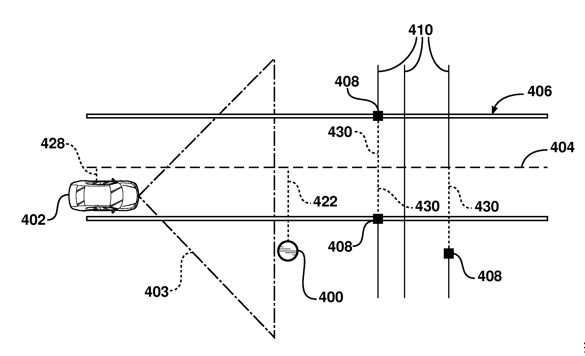
[0058]This invention relates specifically to an improved method and apparatus or system for obtaining an object's position, i.e., of a vehicle on a road, with much greater accuracy than purely through GPS / A-GPS and traditional map matching techniques. The increase in accuracy is not in the physical x, y, z spatial location obtained from GPS, but results from the fact that spatial position relative to some other pre-defined / pre-located physical object can be determined with far greater accuracy than a GPS-derived surface location by means of suitable on-board sensors, like that described above in connection with US 2008 / 0243378. In addition to the known teachings, this invention sets forth an efficient and practical implementation method whereby only one dimension (1D-lateral) relative distance can be used to effect the advantageous attributes of this concept, thereby lowering the cost of electronic processing, storage, and related equipment requirements.

[0059]Mobile mapping vehicles...


PUM


Abstract

A navigation system for use in a vehicle (402). The system includes an absolute position sensor, such as GPS, in addition to one or more additional sensors, such as a camera, laser scanner, or radar. The system further comprises a digital map or database that includes records for at least some of the vehicle's surrounding objects (400). These records can include relative positional attributes with respect to a reference axis (404). As the vehicle (402) moves, sensors sense the presence of at least some of these objects (400), and measure the vehicle's relative position to those objects. This information is used to determine the vehicle's instantaneous lateral offset (428) relative to the reference axis (404), and support features such as enhanced driving directions, collision avoidance, or automatic assisted driving. The system also allows new objects (408, 414) to be attributed using relative positioning, and thereby factored into the enhanced navigation features.

Description

CLAIM OF PRIORITY[0001]None.FIELD OF THE INVENTION[0002]The invention relates generally to digital maps, geographical positioning systems, and vehicle navigation, and particularly to a system and method for vehicle navigation and piloting using absolute and relative coordinates.BACKGROUND[0003]Navigation systems, electronic maps (also referred to herein as digital maps), and geographical positioning devices have been increasingly used in vehicles to assist the driver with various navigation functions, such as: determining the overall position and orientation of the vehicle; finding destinations and addresses; calculating optimal routes (perhaps with the assistance of real time traffic information); and providing real-time driving guidance, including access to business listings or yellow pages. Typically the navigation system portrays a network of streets as a series of line segments, including a centreline running approximately along the centre of each roadway. The moving vehicle ca...

Claims


Application Information

Patent Timeline
Patent Type & Authority Applications(United States)
IPC IPC(8): G01C21/26G01S13/931
CPCG01C21/30G01S13/931G01S19/48G01S13/865G01S13/867G01S2013/936G08G1/16G01C21/26G08G1/09626G08G1/167G06K9/00791G06K9/00798G01S2013/9339G01C21/28B60W30/12G01S2013/9329G01S2013/9316G06V20/56G01S19/485
Inventor MIKSA, KRZYSZTOFSMIECHOWICZ, KRZYSZTOF
Owner TOMTOM POLSKA
Why Eureka
Try Eureka