Listening environments tend to have some amount of background or ambient noise.
This noise is a challenge to sound-system designers, especially when the background or ambient noise is large or has a time-varying intensity.
However, this solution may be insufficient when the noise in a listening area varies over time.
Further, in some listening areas, some factors may be more pronounced than others, especially variable noise sources such as the operation of an air handling unit, vehicle noise, and the like.
The noise measured during a pre-performance calibration might therefore not be a good representation of the ambient or
background noise that occurs during a performance.
Thus, although it may be helpful, a one-time calibration is not a full solution to the challenge of time-varying ambient noise.
This approach involves some additional challenges.
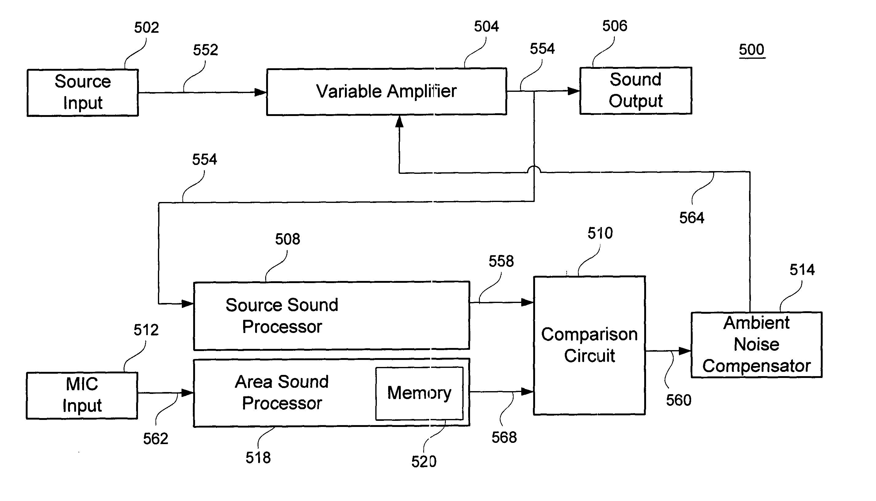
One challenge is to measure the sound level in the listening area and ascertain how much of that sound is noise and how much is from the source signal being projected into the listening area.
Existing systems may fail to take account of the fact that by monitoring the listening area, a measurement
microphone hears the extraneous noise as well as the desired sounds.
Thus, these systems may essentially attenuate the sound being played in response to itself, which is not a desired solution.
The potential error in the r.m.s. computation from this mechanism can exceed the level difference caused by extraneous noise sources in the room.
Because it is based on a time-domain comparison between the source signal and the
microphone signal, this approach is largely insensitive to the frequency distribution of the noise and source signals.
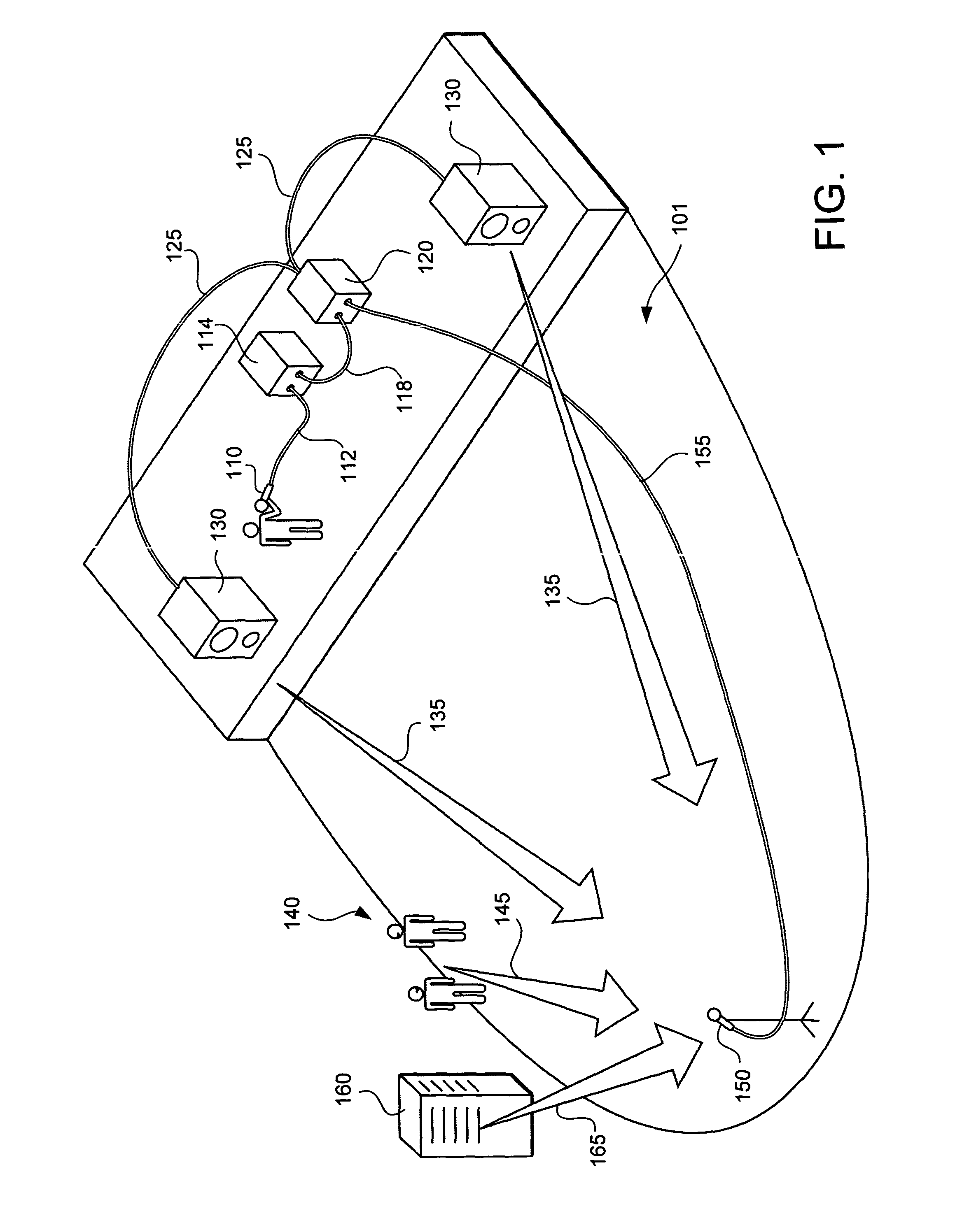
Further, the time
delay for a signal to go from the source, such as a speaker or system of speakers, to the measurement
microphone, is affected by factors such as the number and type of loudspeakers used in a
sound system, placement of the loudspeakers, proximity of the loudspeakers to the measurement microphone, reverberant standing
waves, and multiple signals arriving at the measurement microphone due to signal reflections, signal echoes, and multiple signals due to multiple loudspeakers.
These
delay factors result in a variety of delays known as time smear.
Because of the variety of factors that contribute to these delays, a real-time time-domain approach may be of limited reliability for comparing a
microphone signal to a source signal.
Other approaches are limited to special applications, such as automotive sound systems, where special knowledge of the noise may be obtained from sources other than a
microphone signal.
For example, in the passenger compartment of an automobile, the main sources of extraneous noise include wind, tire noise, and engine noise.
These approaches are not readily adaptable to more general situations, where the main indication of background or ambient noise is a microphone signal or some other input in which noise is combined with a desired sound.

