Automated system and method for identifying and measuring packages transported through a laser scanning tunnel

a laser scanning and tunnel type technology, applied in the direction of instruments, instruments for dispensing discrete objects, electromagnetic radiation sensing, etc., can solve the problems of inability to scan bar code systems in a true omni-directional sense, and the inability to achieve true omni-directional scanning along the principal planes of a large 3-d scanning volume,

Inactive Publication Date: 2002-10-01
METROLOGIC INSTR
View PDF26 Cites 139 Cited by
  • Summary
  • Abstract
  • Description
  • Claims
  • Application Information

AI Technical Summary

Benefits of technology

FIG. 60 is a schematic representation of an automatic package identification and measurement system of the present invention shown interfaced to a relational database management system (RDBMS) and an Internet information server which are connected to a local information network that is interconnected to the Internet, for the purpose of enabling customers and other authorized personnel to use a WWW-enabled browser program to (1)remotely access (from an Internet server) information about any packages transported through the system, as well as diagnostics regarding the system, and (2) remotely control the various subcomponents of the system in order to reprogram its subsystems, perform service routines, performance checks and the like, as well as carry out other forms of maintenance required to keep the system running optimally, while minimizing downtime or disruption in system operations.

Problems solved by technology

While over-the-head laser scanning systems are effective in scanning upwardly-facing bar codes on conveyed objects, there are many applications where it is not practical or otherwise feasible to ensure that bar code labels are upwardly-facing during transportation under the scanning station.
Notably, however, prior art tunnel scanning systems, including the system disclosed in U.S. Pat. No. 5,019,714, are incapable of scanning bar code systems in a true omni-directional sense, i.e. independent of the direction that the bar code faces as it is transported along the conveyor structure.
However, true omnidirectional scanning along the principal planes of a large 3-D scanning volume has not been hitherto possible.
Also, while numerous systems have been proposed for automatically identifying and measuring the dimensions and weight of packages along a high-speed conveyor, prior art systems have been very difficult to manufacture, maintain, and operate in a reliable manner without the use of human supervision.

Method used


Image

  • Automated system and method for identifying and measuring packages transported through a laser scanning tunnel
  • Automated system and method for identifying and measuring packages transported through a laser scanning tunnel
  • Automated system and method for identifying and measuring packages transported through a laser scanning tunnel

Examples


embodiment 1

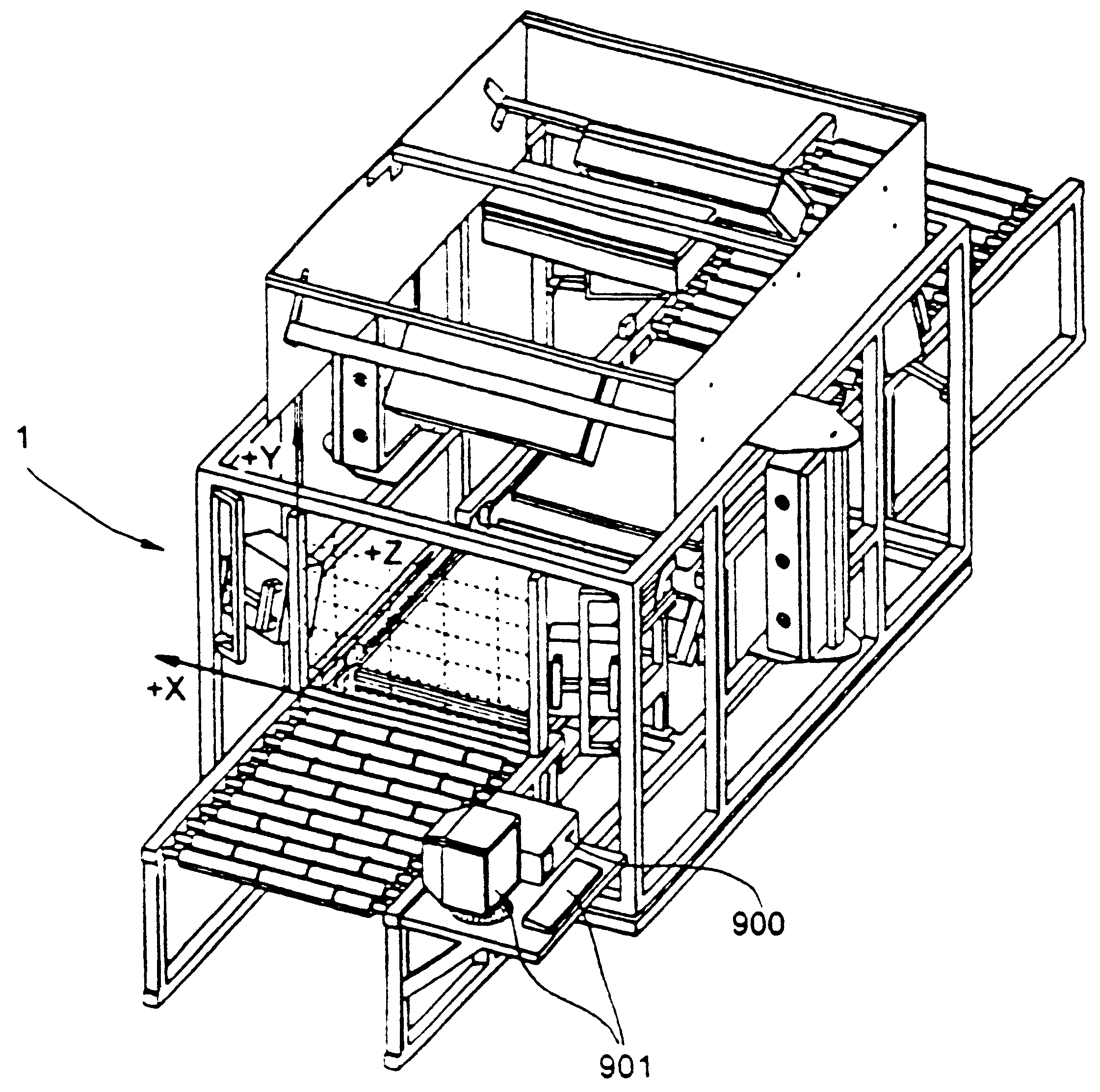
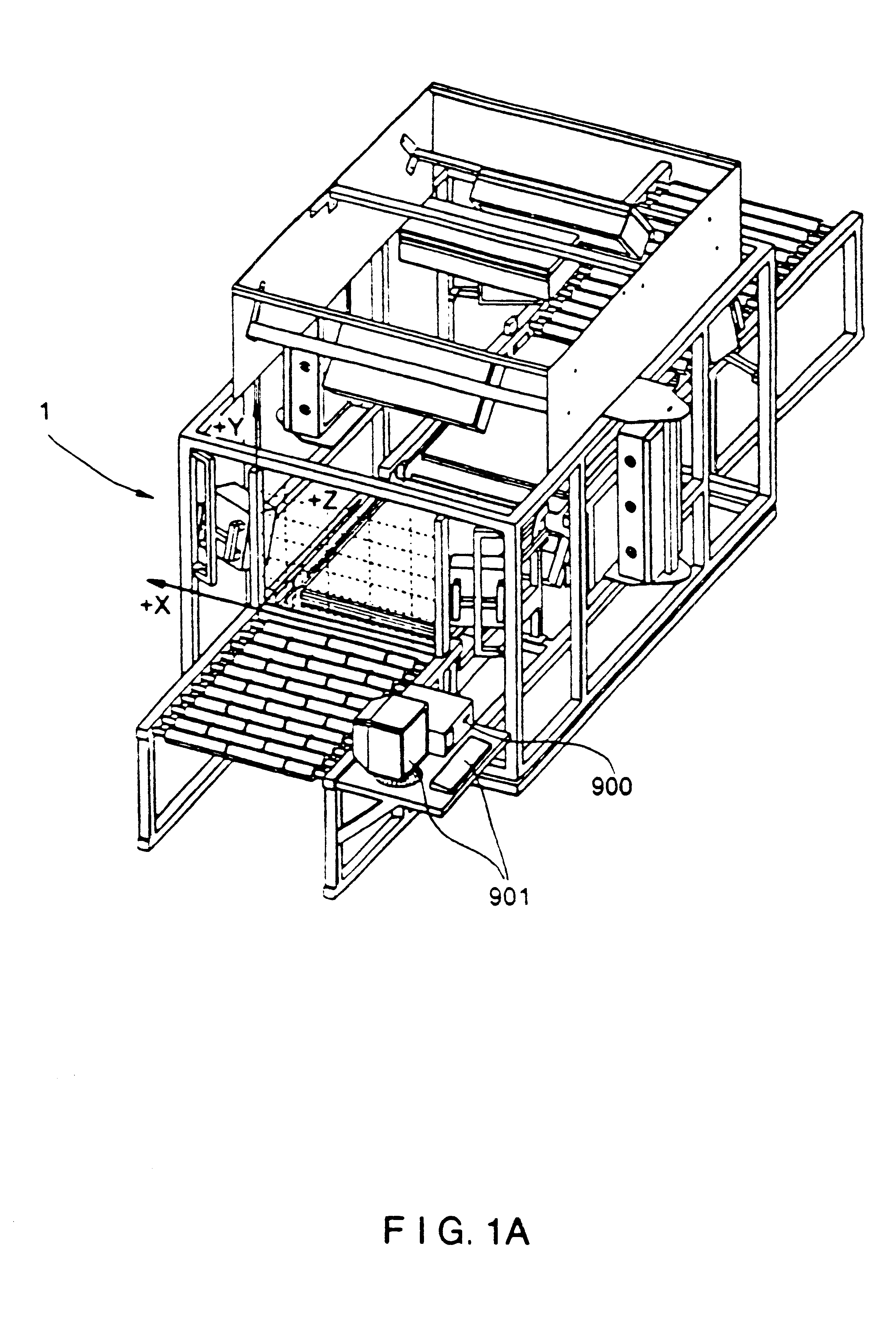
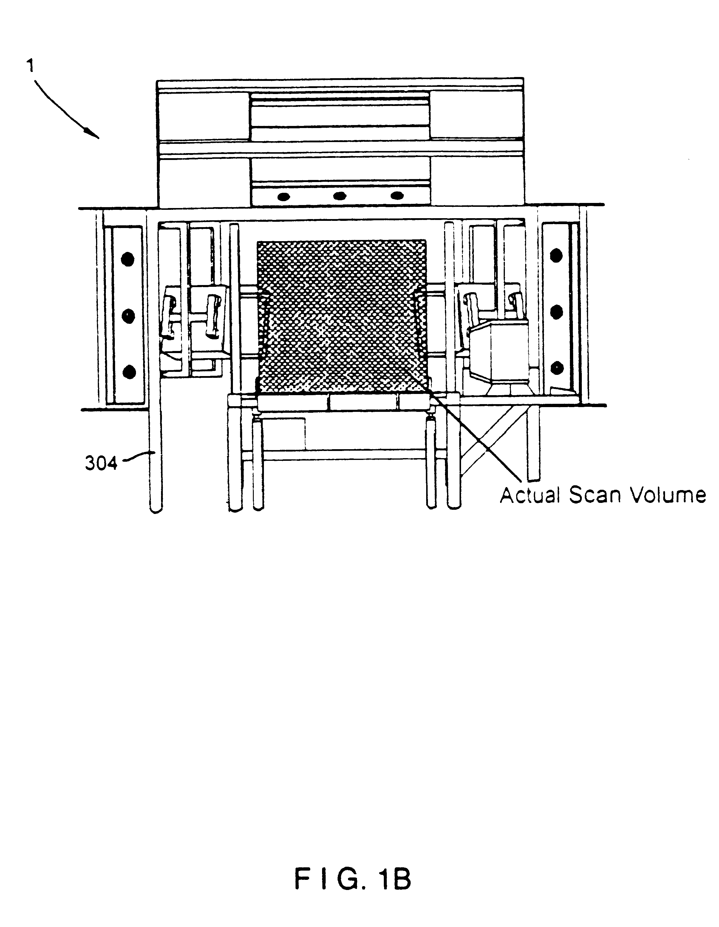
As shown in FIGS. 1A through 1G, the tunnel scanning system of the first illustrative embodiment 1 comprises an arrangement of laser scanning subsystems (i.e. scanners) which, by virtue of their placement, relative to the conveyor belt subsystem 300, essentially form a "tunnel" scanning subsystem over and about the conveyor belt of the conveyor subsystem 300. In the field of package sortation of any sort, whether it be mail, luggage (as in an airport terminal) or other items or boxes, this type of code symbol scanning system is known as a "tunnel scanning system" by those skilled in the art.

The tunnel scanning system of the first illustrative embodiment, shown in great detail in FIGS. 1A through 9B, has been designed and constructed to meet a specific set of customer-defined scanning parameters. For example, the bar code label could be on any one side of a box having six sides. The bar code label could be in any orientation. Furthermore, the object bearing the bar code label to be r...

embodiment 2000

Referring now to FIGS. 33 through 34, the "dual-lane" automated tunnel-type laser scanning system of the second illustrated embodiment 2000 will now be described in detail. As in the first illustrative embodiment depicted in FIGS. 1A through 32B, the system of the second illustrative embodiment is designed to identify and measure packages that are singulated along a conveyor subsystem in a conventional manner.

Overview of the Tunnel Scanning System of the Second Illustrative Embodiment of the Present Invention

As shown in FIGS. 33 and 34, the automated tunnel scanning system of the second illustrative embodiment indicated by reference numeral 2000 comprises an integration of subsystems, namely: a high-speed package conveyor subsystem 2100 having a conveyor belt 2101 having a width of at least 60 inches to support a pair of package transport lanes 2102A and 2102B along the conveyor belt; a pair of dual-disc holographic laser scanning bar code symbol reading subsystems 2200A and 2200B s...


PUM


Abstract

A fully automated package identification and measuring system, in which an omni-directional holographic scanning tunnel is used to read bar codes on packages entering the tunnel, while a package dimensioning subsystem is used to capture information about the package prior to entry into the tunnel. Mathematical models are created on a real-time basis for the geometry of the package and the position of the laser scanning beam used to read the bar code symbol thereon. The mathematical models are analyzed to determine if collected and queued package identification data is spatially and/or temporally correlated with package measurement data using vector-based ray-tracing methods, homogeneous transformations, and object-oriented decision logic so as to enable simultaneous tracking of multiple packages being transported through the scanning tunnel.

Description

1. Field of InventionThe present invention relates generally to an automated tunnel-type laser scanning package identification and measuring system arranged about a high-speed conveyor structure used in diverse package routing and transport applications, and also a method of identifying and measuring packages having bar code symbols on surfaces facing any direction with a 3-D scanning volume.2. Brief Description of the Prior ArtIn many environments, there is a great need to automatically identify and measure objects (e.g. packages, parcels, products, luggage, etc.) as they are transported along a conveyor structure. While over-the-head laser scanning systems are effective in scanning upwardly-facing bar codes on conveyed objects, there are many applications where it is not practical or otherwise feasible to ensure that bar code labels are upwardly-facing during transportation under the scanning station.Various types of "tunnel" scanning systems have been proposed so that bar codes c...

Claims


Application Information

Patent Timeline
Patent Type & Authority Patents(United States)
IPC IPC(8): G02B26/10G07G1/00G06K17/00G06K7/10G06K7/14
CPCG02B26/106G06K7/10G06K7/10564G06K7/10584G06K7/10594G06K7/10603G06K7/10663G06K7/10673G06K7/10693G06K7/10702G06K7/10792G06K7/10801G06K7/10811G06K7/10851G06K7/10861G06K7/10871G06K7/10881G06K7/10891G06K7/109G06K7/14G06K17/0022G07F11/002G07G1/0054G06K2207/1013G07F9/002
Inventor GOOD, TIMOTHY A.ZHU, XIAOXUNWILZ, DAVID M.ROCKSTEIN, GEORGE B.COLAVITO, STEPHEN J.BLAKE, ROBERT E.AU, KA MANGHOSH, SANKARKOLIS, GEORGESCOTT, IAN A.AMUNDSEN, THOMASGERMAINE, GENNADYDEHENNIS, ANDREW D.DICKSON, LEROYKNOWLES, CARL HARRY
Owner METROLOGIC INSTR
Why Eureka
Try Eureka