
Electromagnetic interference spring contact for shielding electromagnetic interference and electronic device using same

Inactive Publication Date: 2012-04-24
FU TAI HUA IND SHENZHEN +1
View PDF3 Cites 14 Cited by
  • Summary
  • Abstract
  • Description
  • Claims
  • Application Information

AI Technical Summary

Problems solved by technology

So, two or more EMI spring contacts are needed to connect the circuit board assemblies by screws which is inconvenient.

Method used


Image

  • Electromagnetic interference spring contact for shielding electromagnetic interference and electronic device using same
  • Electromagnetic interference spring contact for shielding electromagnetic interference and electronic device using same
  • Electromagnetic interference spring contact for shielding electromagnetic interference and electronic device using same

Examples


Embodiment Construction

[0013]Embodiments of the present disclosure will now be described in detail below, with reference to the accompanying drawings.

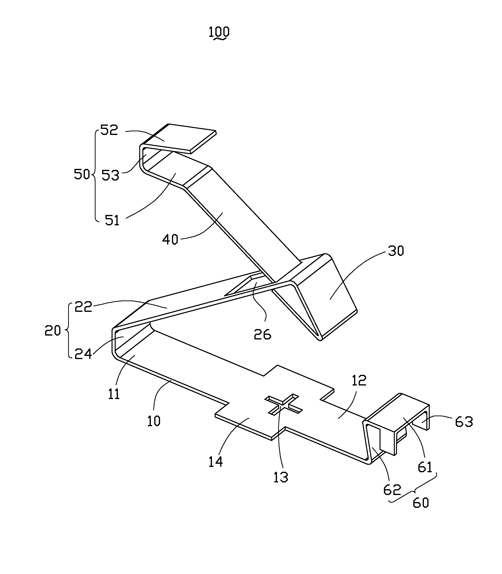
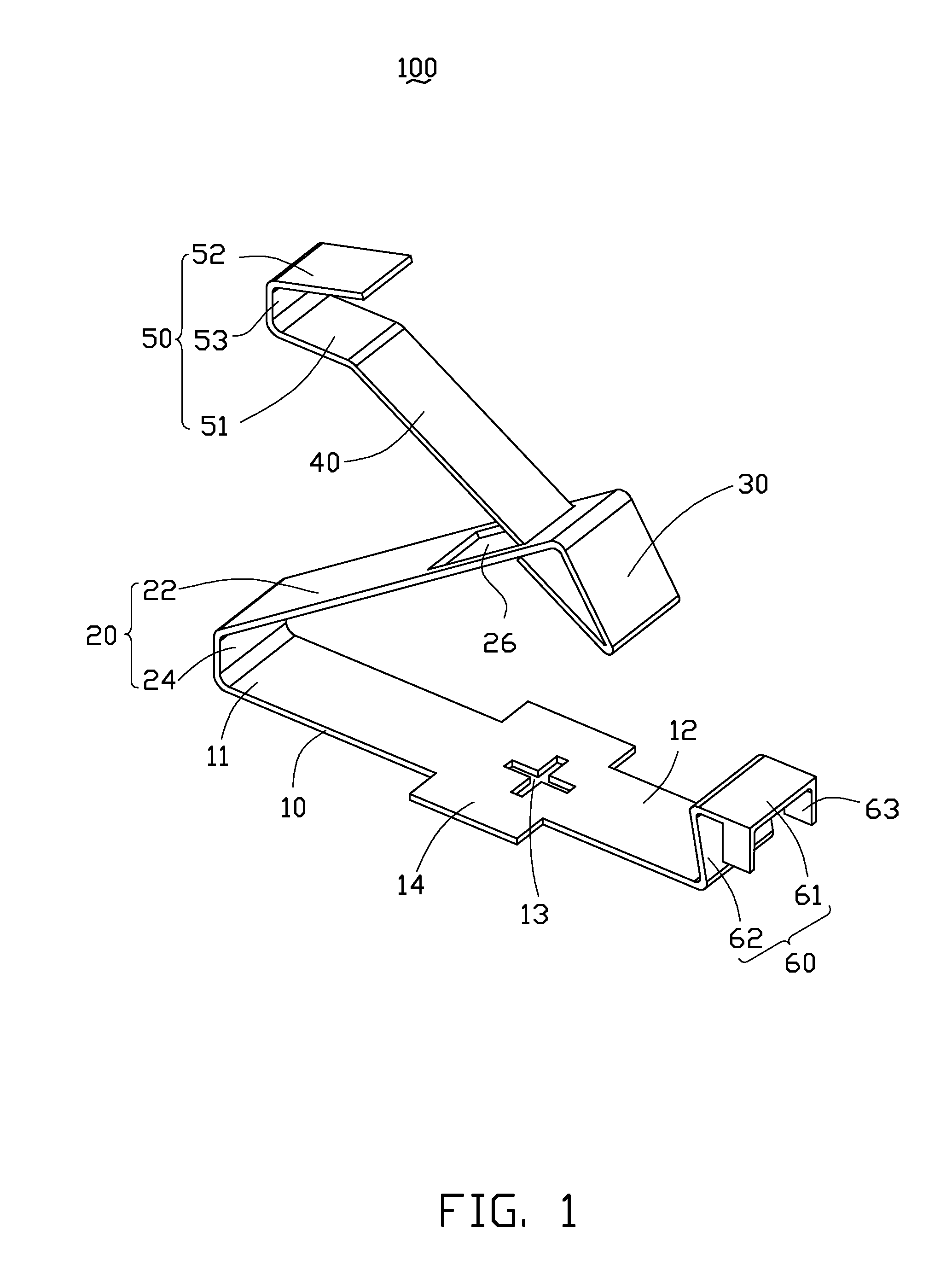
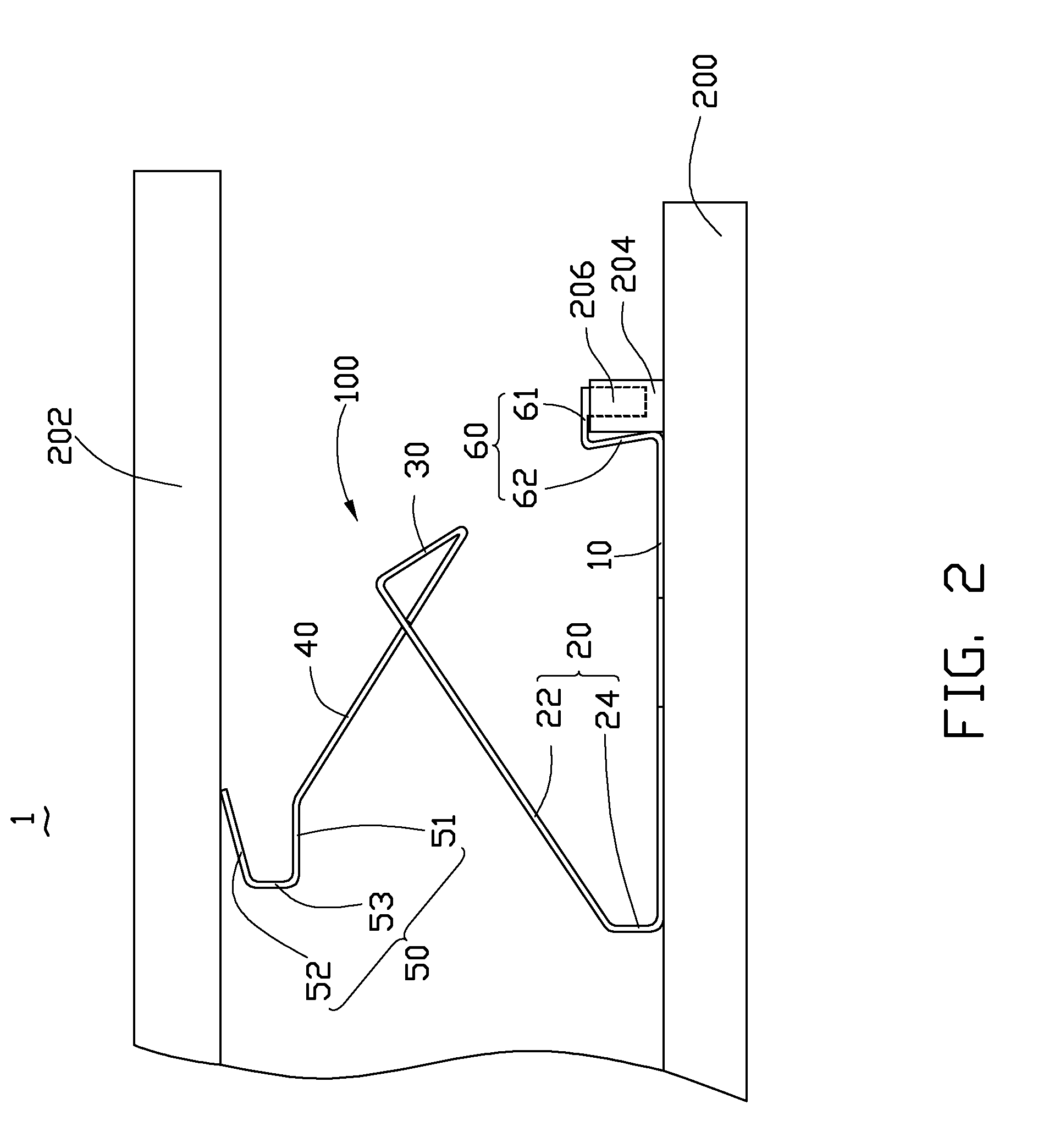
[0014]Referring to FIG. 1, an EMI spring contact 100 according to an exemplary embodiment is illustrated. The EMI spring contact 100 includes a first section 10 having a first end 11 and a second end 12 opposite to the first end 11, a second section 20 connected to the first section 10 and extending up and angularly from the first end 11 of the first section 10, a third section 30 connected to the second section 20 and extending down from the second section 20, a fourth section 40 connected to the third section 30 and extending up and angularly from the third section 30, a fifth section 50 connected to the fourth section 40 and a sixth section 60 connected to the second end 12 of the first section 10.

[0015]The first section 10 may be strip shaped. A first crisscross through hole 13 is defined in the center of the first section 10. The first through hole 13 i...


PUM


Abstract

An EMI spring contact for shielding EMI comprises a first section having a first end and a second end opposite to the first end, a second section connected to the first section and extending up and angularly from the first end of the first section, a third section connected to the second section and extending down from the second section, and a fourth section connected to the third section. An acute angle is formed between the first and second sections, and a first through hole is defined in the second section. The fourth section extends up and angularly from the third section through the first through hole of the second section and is movably received in the first through hole.

Description

BACKGROUND[0001]1. Technical Field[0002]The present disclosure relates to an electro-magnetic interference (EMI) spring contact for shielding against EMI.[0003]2. Description of Related Art[0004]EMI spring contacts are known in the art, they are used between a circuit board assembly and a conductive member of the electronic device. Most of the time the EMI spring contacts are connected to the circuit board assembly by screws. Nowadays, electronic devices are designed with more and more complexity, and two or more circuit board assemblies may be used. So, two or more EMI spring contacts are needed to connect the circuit board assemblies by screws which is inconvenient.[0005]Therefore, there is room for improvement in the art.BRIEF DESCRIPTION OF THE DRAWINGS[0006]The components in the drawings are not necessarily drawn to scale, the emphasis instead being placed upon clearly illustrating the principles of the EMI spring contacts. Moreover, in the drawings, like reference numerals des...

Claims


Application Information

Patent Timeline
Patent Type & Authority Patents(United States)
IPC IPC(8): H01R12/00H05K1/00
CPCH05K9/0064
Inventor CHEN, SONG-YA
Owner FU TAI HUA IND SHENZHEN
Learn More