

Laser device
a laser device and laser technology, applied in the field of laser devices, can solve the problems of frequent fine-tuning adjustments or inaccurate orientation of the horizontal plane of rotation
- Summary
- Abstract
- Description
- Claims
- Application Information
AI Technical Summary
Benefits of technology
Problems solved by technology
Method used
Image

Examples
Embodiment Construction
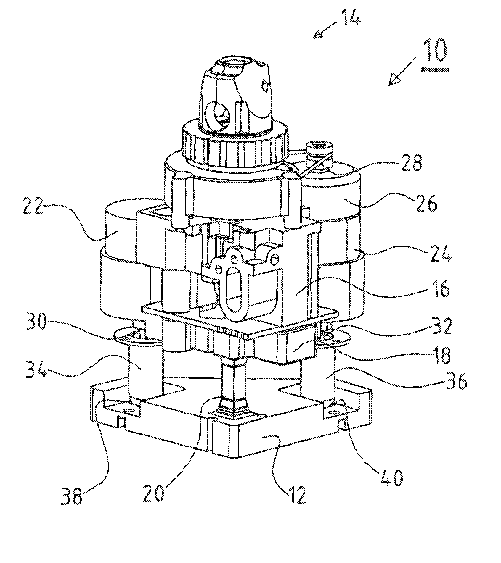
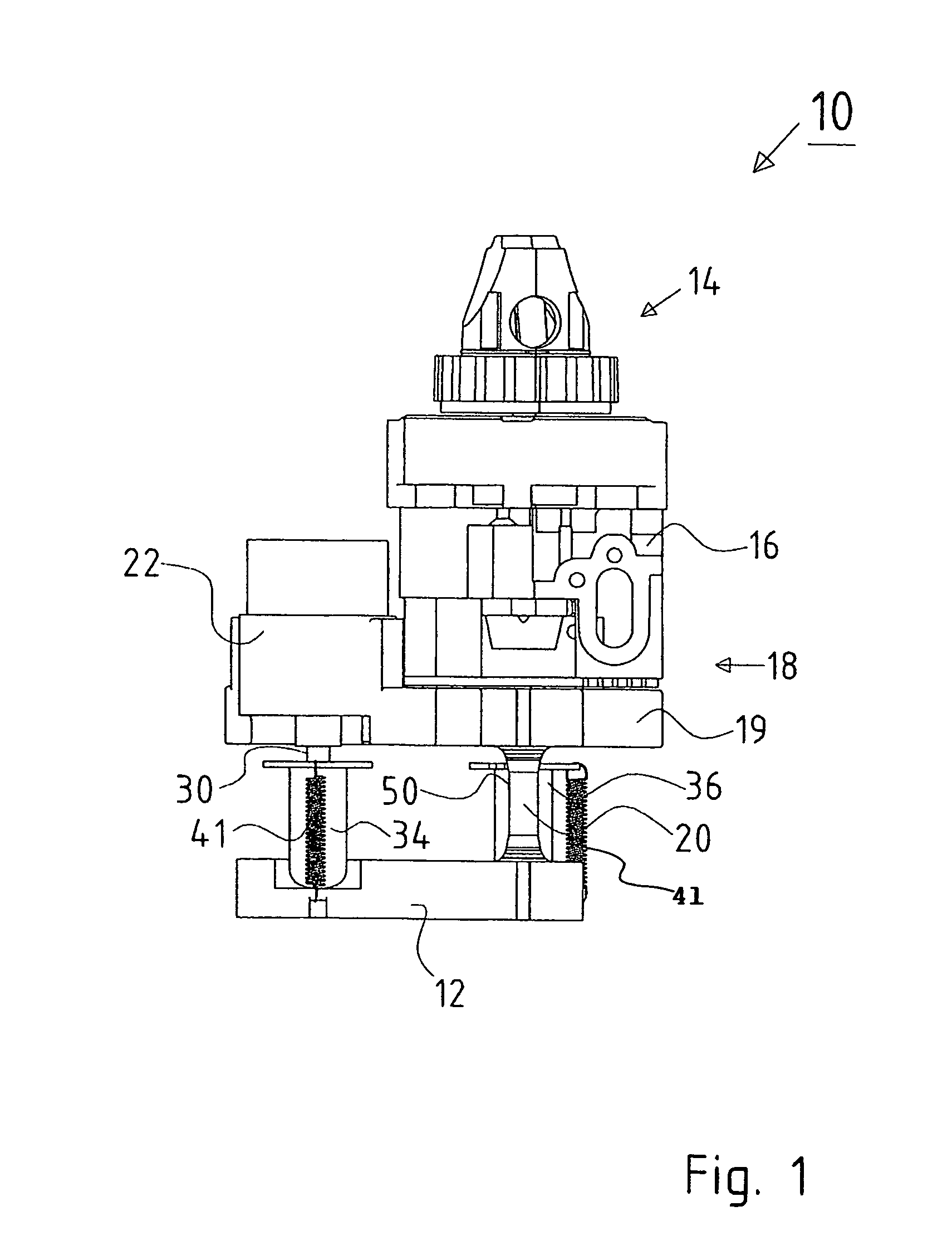
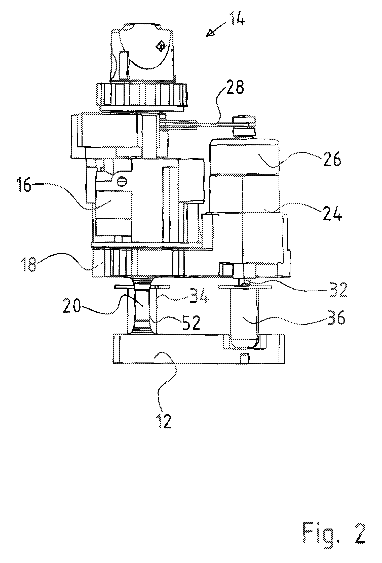
[0036]The invention will now be explained by means of a rotation laser, without this limiting the invention. The figures, in which the same elements are provided with the same reference numbers, show the inner part, i.e., the core of the rotation laser, which is indicated by the reference 10 and arranged in an outer housing of the laser (not shown). A corresponding rotation laser, also called a rotation construction laser, comprising a laser beam rotating at least by segments, is used in the construction industry, for example, in order to determine a defined inclined plane, especially a horizontally extending plane. For this, a laser beam is emitted by a laser unit, which is deflected by around 90 degrees by a deflection device, which in turn is mounted so that it can turn in a rotation head. The axis of rotation intersects the axis of the deflected laser beam. The deflection device can be, e.g., a pentaprism. It must be possible to adjust the laser unit with the rotation head to th...
PUM
 Abstract
Description
Claims
Application Information