Image sensing apparatus and imaging system

a technology of image sensing apparatus and imaging system, which is applied in the direction of color television details, television system details, television systems, etc., can solve the problems of difficult to meet both of these requirements, and achieve the effect of reducing the noise contained in fixed pattern noise and speeding up the readout operation of signals

Inactive Publication Date: 2012-05-08
CANON KK
View PDF32 Cites 19 Cited by
  • Summary
  • Abstract
  • Description
  • Claims
  • Application Information

AI Technical Summary

Benefits of technology

[0007]The present invention provides for speeding up the readout operation of a signal from a pixel to an output amplifier, and for reducing fixed pattern noise contained in an image signal.
[0010]The present invention can speed up the readout operation of a signal from a pixel to an output amplifier, and reduce fixed pattern noise contained in an image signal.

Problems solved by technology

It is generally difficult to meet both of these two requirements.

Method used


Image

  • Image sensing apparatus and imaging system
  • Image sensing apparatus and imaging system
  • Image sensing apparatus and imaging system

Examples


first embodiment

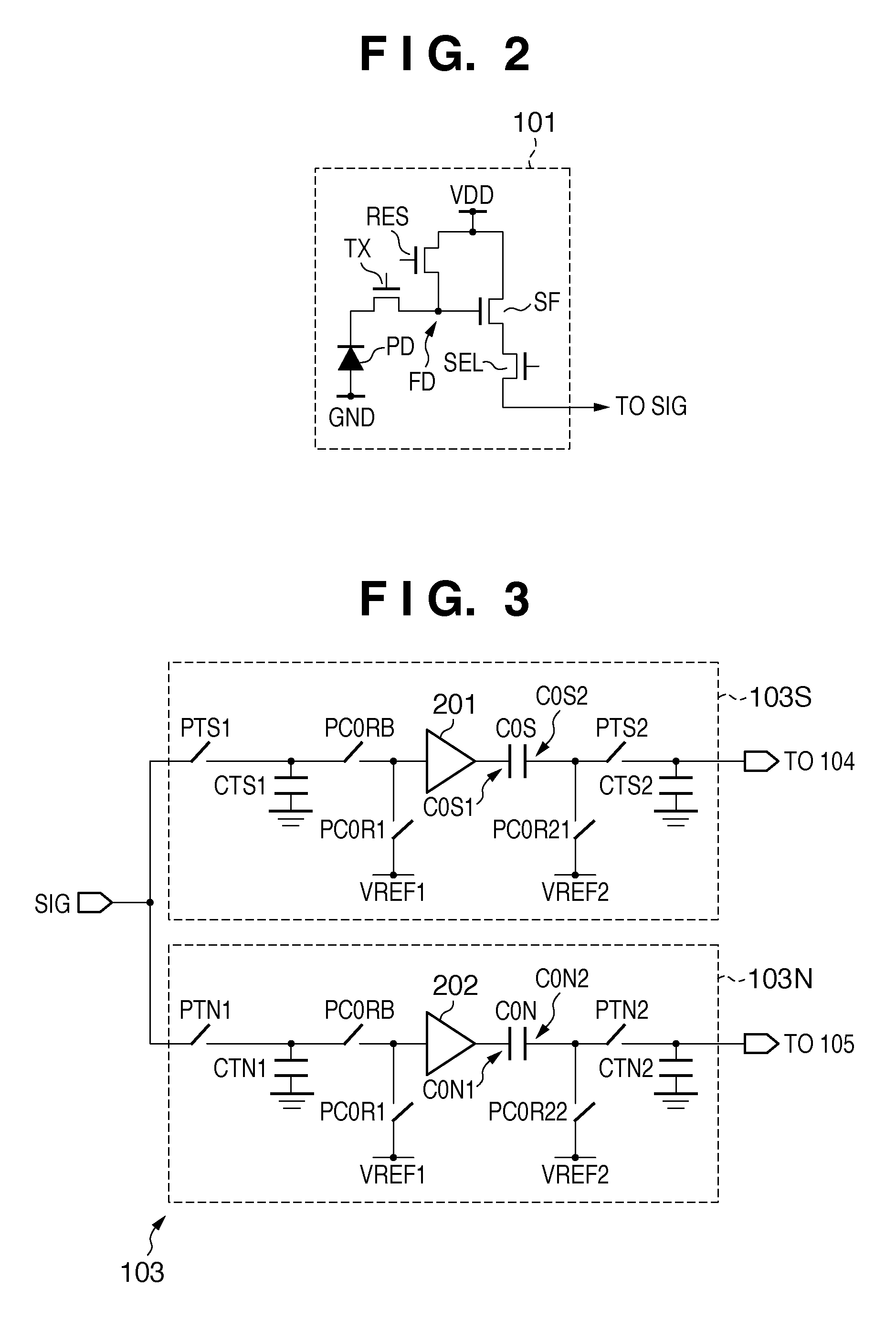
[0137]The optical signal transfer unit 103Si includes a switch PC0RB1i, switch PC0RB2i, first impedance converter (first differential amplifier) 401i, switch PC0R3i, and first clamp capacitance C0Si, unlike the

[0138]The switch PC0RB1i is turned on to transfer an optical signal held in a first holding unit CTS1 to a first electrode C0S1i of the first clamp capacitance C0Si.

[0139]The switch PC0RB2i is turned on to transfer a signal supplied from a second electrode C0S2i of the first clamp capacitance C0Si to the non-inverting input terminal of the first impedance converter 401i.

[0140]The first impedance converter 401i includes a differential amplifier as shown in FIG. 25 that functions as a voltage follower as shown in FIG. 24.

[0141]The first clamp capacitance C0Si can be connected via a switch PC0R3i to a line connecting an output node N1 of the first impedance converter 401i and a second holding unit CTS2.

[0142]The switch PC0R3i connects / disconnects the output node N1 of the first ...

second embodiment

[0161]However, in the second embodiment, no clamp capacitance attenuates the signal amplitude. The output amplifier can therefore operate at low gain which hardly generates noise.

[0162]In the readout circuit, a signal passing through the column signal line SIG may also directly charge the clamp capacitances C0Si and C0Ni without arranging the first holding unit CTS1 and third holding unit CTN1. In this case, when the switches PTN1 and PTS1 are turned off, the electrodes of the clamp capacitances C0Si and C0Ni on the sides of the switches PTN1 and PTS1 electrically float. If disturbance noise is mixed in the floating electrodes, it directly appears in the outputs of the impedance converters 401i and 402i. That is, the adverse effect of disturbance noise can be reduced by arranging the first holding unit CTS1 and third holding unit CTN1 in the readout circuit.

[0163]An image sensing apparatus 100j according to the third embodiment will be described. A difference from the first embodime...

third embodiment

[0191]CTS11 and CTN11 in the third embodiment can also be omitted.

[0192]An image sensing apparatus 100k according to the fourth embodiment will be described. A difference from the third embodiment will be mainly explained.

[0193]The structure of a readout circuit 103j on each column in the image sensing apparatus 100k is similar to that in the third embodiment. However, the operation of the readout circuit on each column is different from that in the third embodiment in that a gain is applied using an impedance converter, as shown in FIG. 14. FIG. 14 is a timing chart showing the operation of the readout circuit 103j on each column in the image sensing apparatus 100k according to the fourth embodiment of the present invention.

[0194]At time t30 in the vertical transfer period VT(N), a vertical scanning circuit 110 supplies an active-level control signal φPTS1 to a switch PTS1 of an optical signal transfer unit 103Sj on each column. Then, the switch PTS1 is turned on to transfer, to ho...


PUM


Abstract

An image sensing apparatus comprises a transfer block including a first transfer unit and a second transfer unit, wherein the first transfer unit includes a first impedance converter which transfers a first signal to the output unit, and the first transfer unit transfers, as a third signal, a difference signal between a first offset of the first impedance converter and a signal obtained by superimposing the first offset on the first signal, the second transfer unit includes a second impedance converter which transfers a second signal to the output unit, and the second transfer unit transfers, as a fourth signal, a difference signal between a second offset of the second impedance converter and a signal obtained by superimposing the second offset on the second signal, and the output unit calculates a difference between the third signal and the fourth signal, generating and outputting an image signal.

Description

BACKGROUND OF THE INVENTION[0001]1. Field of the Invention[0002]The present invention relates to an image sensing apparatus and imaging system.[0003]2. Description of the Related Art[0004]In an image sensing apparatus disclosed in Japanese Patent Laid-Open No. 11-150255, a capacitance C, amplifier 2, switch SW, capacitance Csh, and amplifier 5 are connected, in the order named, to a signal line SIG, which is connected to pixels on each column in a pixel array, as shown in FIG. 28. In this image sensing apparatus, a reset switch 1 resets the capacitance C in accordance with a reset signal “rc”, as shown in FIG. 29. Then, a thin-film transistor T is turned on, in accordance with a transfer signal “gx”, to transfer the signal of a photoelectric conversion element S to the capacitance C, and the signal is stored in the capacitance C. After that, when the switch SW is turned on in response to a pulse “smpl”, the amplifier 2 amplifies the signal stored in the capacitance C. The amplified ...

Claims


Application Information

Patent Timeline
Patent Type & Authority Patents(United States)
IPC IPC(8): H04N5/335H04N5/341H04N5/357H04N5/363H04N5/369H04N5/374H04N5/3745H04N5/376H04N5/378
CPCH04N3/1568H04N5/378H04N5/365H04N3/1575H04N25/67H04N25/75
Inventor OGURA, MASANORIKOIZUMI, TORUKIKUCHI, SHINRYOKI, TATSUYA
Owner CANON KK
Why Eureka
Try Eureka