Water conservancy monitoring device for water conservancy project

A technology for monitoring devices and water conservancy projects, applied in measuring devices, open-air water source surveys, surveying and mapping, and navigation, etc., can solve problems such as unrepresentative, unsafe, cumbersome operations, etc., and achieve easy detection, use, and observation Record and improve the effect of operation progress

Inactive Publication Date: 2021-08-27
金晨辉
View PDF0 Cites 0 Cited by
  • Summary
  • Abstract
  • Description
  • Claims
  • Application Information

AI Technical Summary

Problems solved by technology

[0004] The purpose of the present invention is to provide a water conservancy monitoring device for water conservancy projects to solve the problem in the above background technology that when detecting current water conservancy projects, it is necessary to detect and record the depth and flow velocity of the water body. The traditional water body depth is to use The manual feeding and winding of the rope body makes the operation very cumbersome and unsafe. People standing by the water may slip and fall, and the flow velocity of the water body is determined by the flow velocity on the surface of the water body. , making it unrepresentative, and both of them need to be detected and processed separately, which makes the operation process complicated and is not conducive to the operation progress of the current water conservancy project, which greatly affects the progress of the water conservancy project.

Method used


Image

  • Water conservancy monitoring device for water conservancy project
  • Water conservancy monitoring device for water conservancy project
  • Water conservancy monitoring device for water conservancy project

Examples


Embodiment Construction

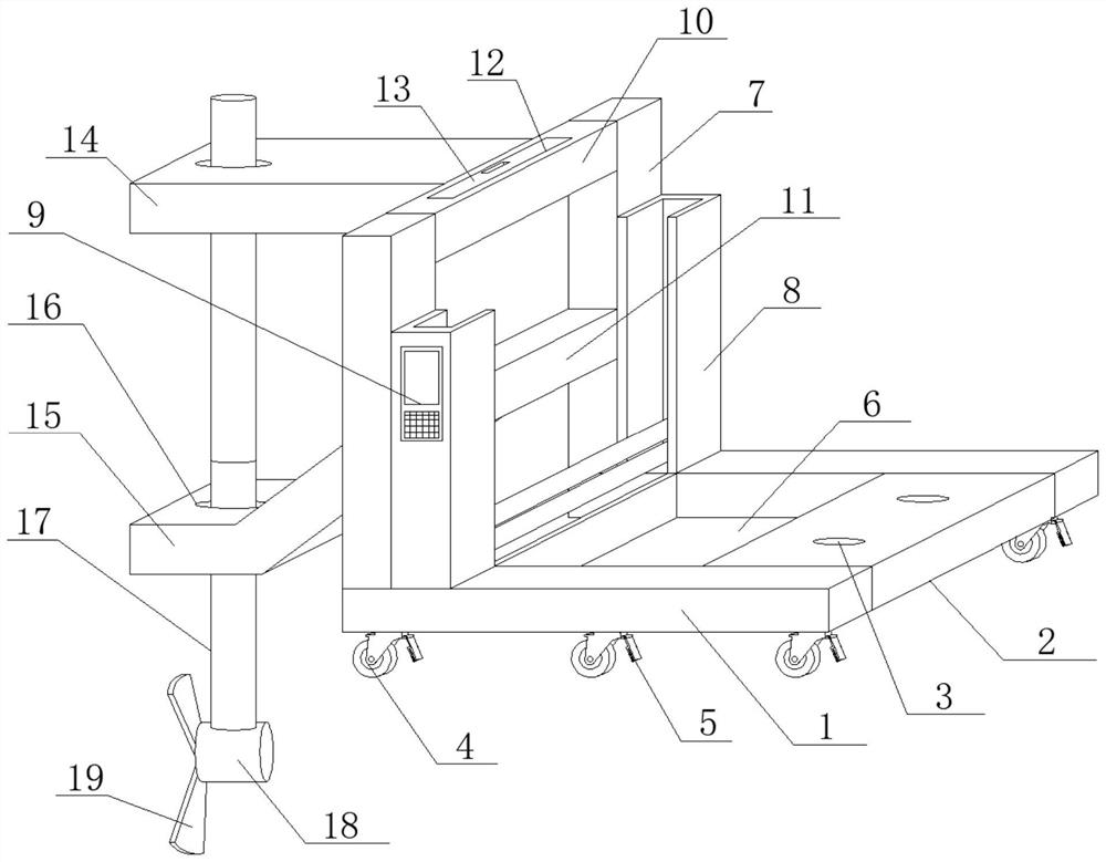
[0027] see Figure 1-2, in an embodiment of the present invention, a water conservancy monitoring device for water conservancy projects, comprising support side rods 1, a counterweight bottom plate 2 is welded horizontally on the sides between the support side rods 1, and the top surface of the counterweight bottom plate 2 is evenly opened with through holes 3. The bottom surface of the supporting side rod 1 is bolted to the moving wheel 4, the side of the moving wheel 4 is provided with a brake plate 5, the number of supporting side rods 1 is two, and the two supporting side rods 1 are arranged parallel to each other , the counterweight bottom plate 2 is horizontally fixed and fixed on the side between the supporting side bars 1 near one end, the number of moving wheels 4 is multiple, and the plurality of moving wheels 4 are evenly arranged in a straight line on the two supporting side bars 1 One end of the brake plate 5 is obliquely inserted into the inner side of the moving...


PUM


Abstract

The invention discloses a water conservancy monitoring device for a water conservancy project, and relates to the field of water conservancy projects. The water conservancy monitoring device comprises supporting side rods, a counterweight bottom plate is horizontally welded to one side edge between the supporting side rods, through holes are uniformly formed in the top surface of the counterweight bottom plate, moving wheels are connected to the bottom surfaces of the supporting side rods through bolts, brake plates are arranged on the side edges of the moving wheels, a storage box body is horizontally connected to the side edge between the supporting side rods through bolts, supporting vertical rods are vertically and upwards welded to the top faces of the supporting side rods, storage side plates are connected to the side edges, close to the balance weight bottom plate, of the supporting vertical rods through bolts, a control panel is embedded in one side edge of one of the storage side plates, and a fixed ejector rod is horizontally welded to the side edge between the supporting vertical rods. According to the device, the split structure is simple; a buckling mode is adopted, so that installation is easy, convenient and efficient; and multiple functions are combined, detection and use are more convenient, and the operation progress of the water conservancy project is greatly accelerated.

Description

technical field [0001] The invention relates to the technical field of water conservancy projects, in particular to a water conservancy monitoring device for water conservancy projects. Background technique [0002] Water conservancy projects are projects built to control and allocate natural surface water and groundwater to achieve the purpose of eliminating harm and rejuvenating profits. Also known as water engineering. Water is an indispensable precious resource for human production and life, but its natural state does not fully meet human needs. Only by building water conservancy projects can we control water flow, prevent floods, and regulate and distribute water to meet the needs of people's life and production for water resources. Water conservancy projects need to build different types of hydraulic structures such as dams, dikes, spillways, sluices, water inlets, channels, canals, rafts, and fishways to achieve their goals. [0003] For the detection of current wa...

Claims


Application Information

Patent Timeline
Patent Type & Authority Applications(China)
IPC IPC(8): G01P5/00G01C13/00F16M11/04F16M11/42
CPCF16M11/04F16M11/42G01C13/008G01P5/00
Inventor 金晨辉
Owner 金晨辉
Why Eureka
Try Eureka