Dispensing module and method of dispensing with a pneumatic actuator

a technology of pneumatic actuator and dispensing module, which is applied in the direction of valve operating means/releasing devices, liquid transfer devices, transportation and packaging, etc., can solve the problems of uneven air flow entering the piston chamber, affecting the performance of current pneumatically actuated dispensing modules, and taking more time to fully pressurize the piston. , to achieve the effect of speeding up the operation and movemen

Inactive Publication Date: 2013-05-02
NORDSON CORP
View PDF36 Cites 0 Cited by
  • Summary
  • Abstract
  • Description
  • Claims
  • Application Information

AI Technical Summary

Benefits of technology

[0012]In yet another aspect, the piston divides the piston chamber into first and second piston chamber portions. In such embodiments, the pneumatic valve element may also include a second inlet passage and a second exhaust passage. As a result, the method also includes passing pressurized air from the air supply inlet through the second inlet passage to pressurize the second piston chamber portion when the pneumatic valve element is moved to the second position (the first piston chamber portion is exhausted at this time). The method further includes passing pressurized air out of the piston chamber through the second exhaust passage to the air exhaust outlet when the pneumatic valve element is moved to the first position. Thus, the first and second piston chamber portions can be alternatively and simultaneously pressurized and exhausted to speed up the operation and movement of the piston and the dispenser valve member between open and closed positions.

Problems solved by technology

The necessary amount of time to shift the valve between open and closed positions increases as a result of the additional time needed by the solenoid to reverse operation and the additional time necessary to reverse flow in the same passages.
Moreover, the performance of current pneumatically actuated dispensing modules may be hindered by uneven air flow where the pressurized air enters and exits at one side of the piston chamber.
The uneven air flow entering the piston chamber takes more time to fully pressurize the piston chamber to force the piston to move.
In this regard, the uneven air flow further increases the necessary amount of time to shift the valve between open and closed positions.

Method used


Image

  • Dispensing module and method of dispensing with a pneumatic actuator
  • Dispensing module and method of dispensing with a pneumatic actuator
  • Dispensing module and method of dispensing with a pneumatic actuator

Examples


Embodiment Construction

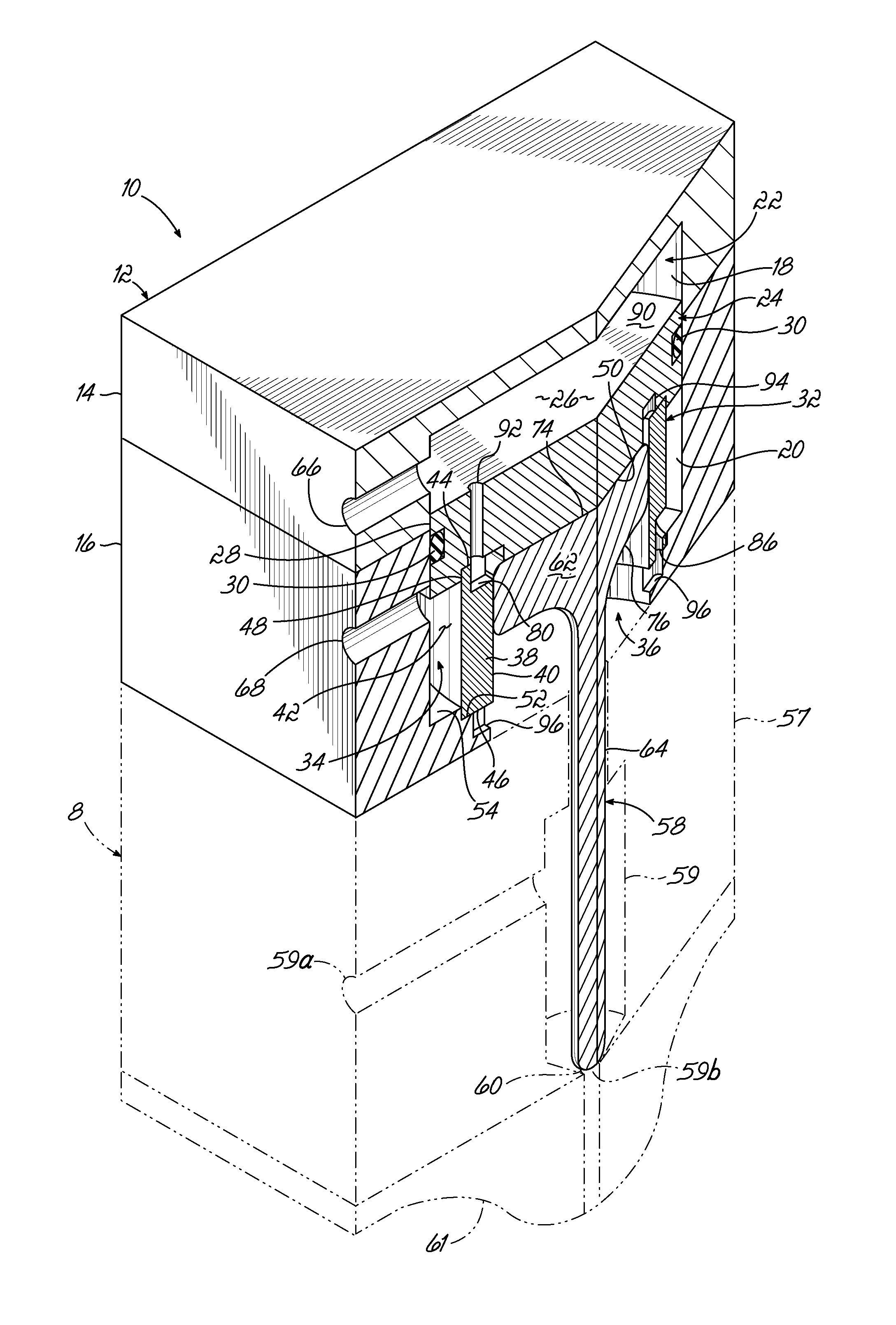
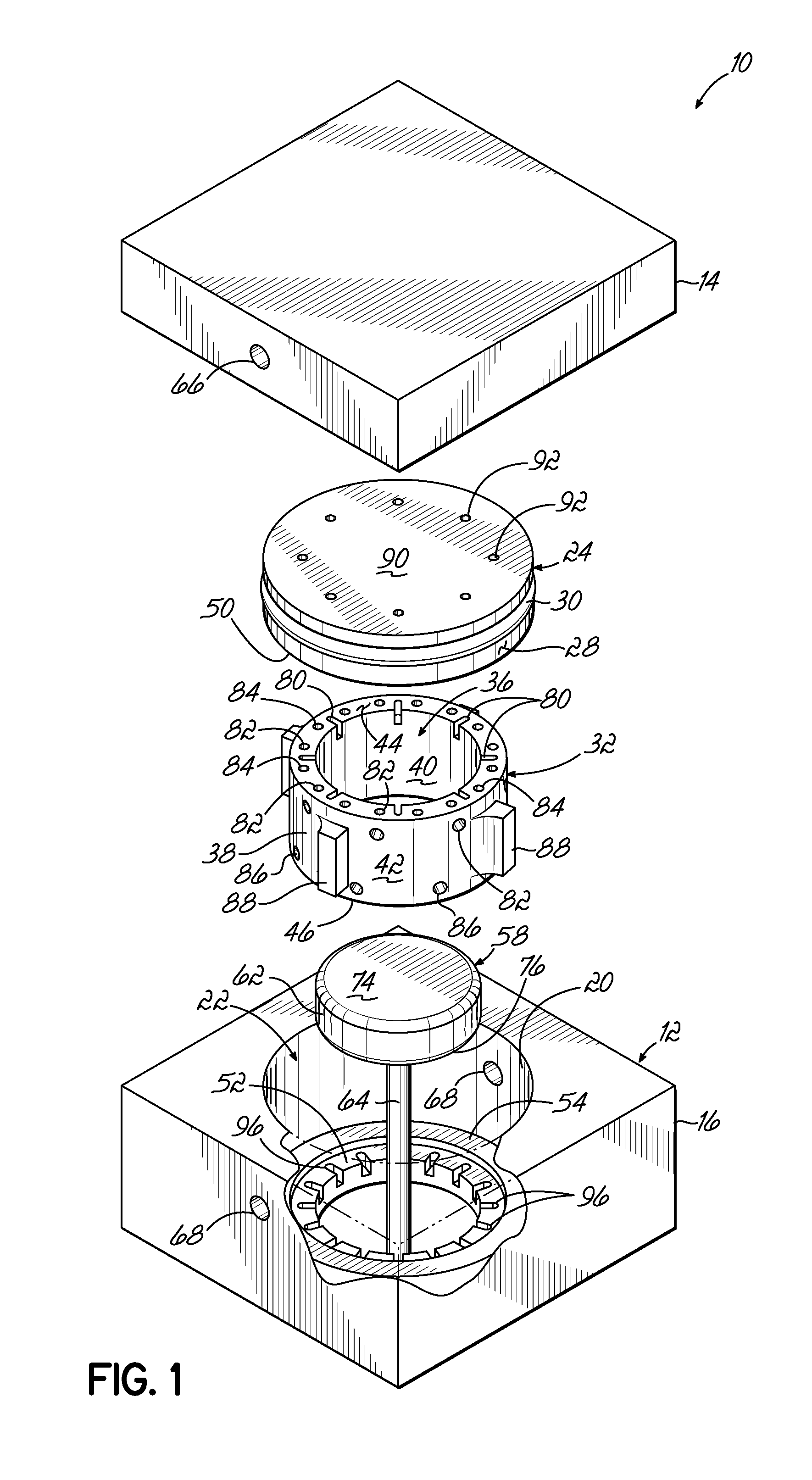
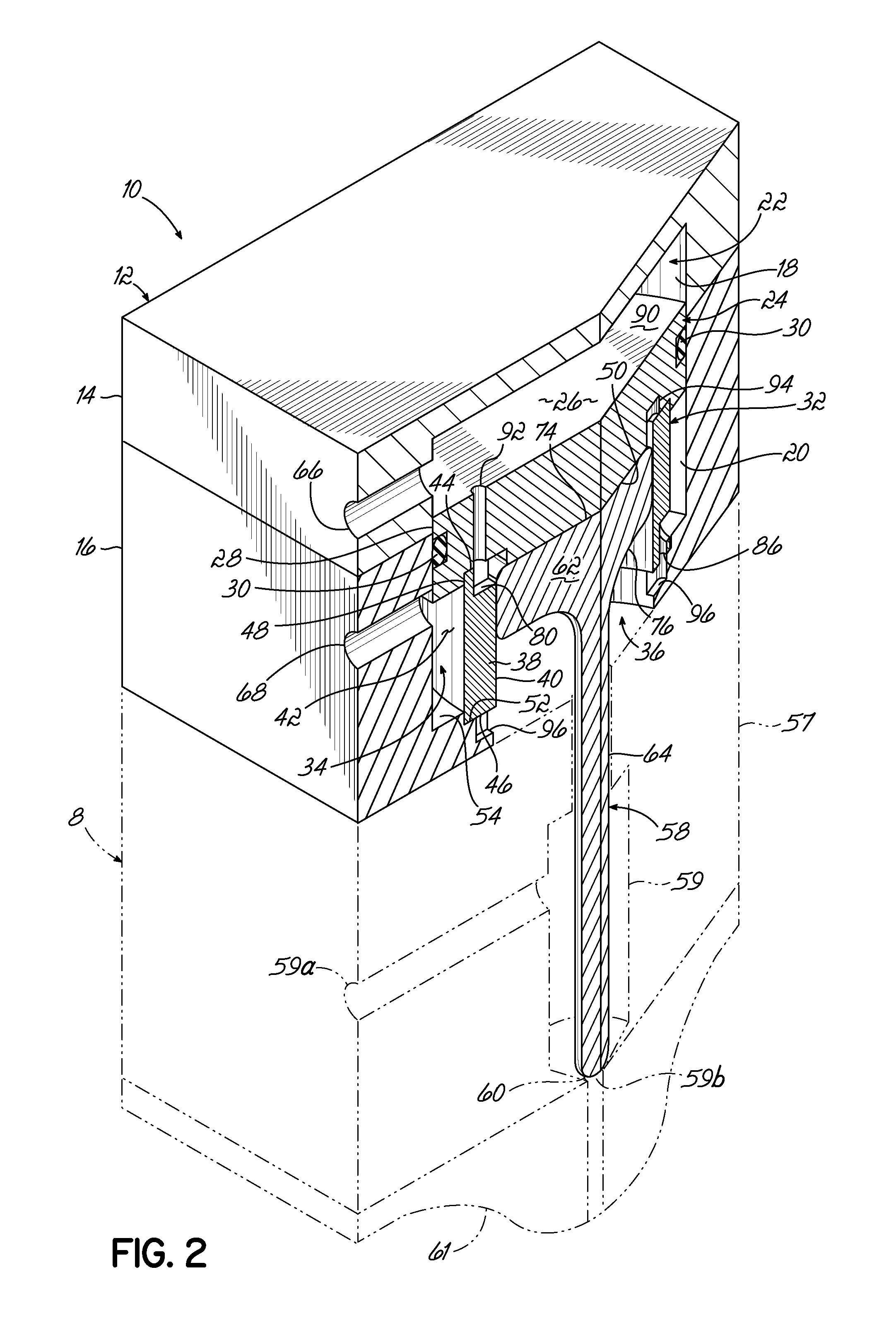
[0034]An exemplary embodiment of a dispensing module 8 including a pneumatic actuator 10 in accordance with the invention is illustrated in FIGS. 1-5D. With specific reference to FIGS. 1 and 2, the actuator 10 includes a pneumatic housing 12 having an upper housing portion 14 and a piston housing portion 16. The upper housing portion 14 includes an upper housing bore 18 and the piston housing portion 16 includes a piston housing bore 20 generally aligned with the upper housing bore 18 when the pneumatic housing 12 is assembled as shown in FIG. 2. In this regard, the upper housing bore 18 and the piston housing bore 20 collectively define an interior cavity 22 of the pneumatic housing 12. The interior cavity 22 is shown having a cylindrical shape in the exemplary embodiment, but it will be understood that the cross-sectional shape of the interior cavity 22 may be modified in other embodiments within the scope of this invention. The pneumatic housing 12 may be formed from a relatively...


PUM


Abstract

An adhesive dispensing module includes a pneumatic actuator for actuating reciprocating movement of a piston on a dispenser valve member. The pneumatic actuator includes a valve element and a pneumatic housing with an inlet chamber, an exhaust chamber, and a piston chamber. The valve element includes a plurality of inlet passages and a plurality of exhaust passages. The valve element rotates from a first position in which the inlet passages deliver pressurized air from the inlet chamber to the piston chamber, to a second position in which the exhaust passages exhaust pressurized air from the piston chamber to the exhaust chamber. The valve element also includes a plurality of fins configured to be driven by an electromagnetic coil to move the valve element.

Description

CROSS-REFERENCE TO RELATED APPLICATION[0001]This application claims the priority of Application Ser. No. 61 / 552,503, filed Oct. 28, 2011 (pending), the disclosure of which is hereby incorporated by reference herein.FIELD OF THE INVENTION[0002]The present invention generally relates to adhesive dispensing modules and methods, and more particularly, to a pneumatic actuator for moving a piston in an adhesive dispensing module.BACKGROUND[0003]In many adhesive dispensing modules, the flow of adhesive material is controlled by a dispenser valve member that moves between open and closed positions. In these modules, the dispenser valves typically include pistons that are pneumatically actuated to move by pressurized air. It is important that the pistons responsible for controlling the flow of material move quickly and reliably between the open and closed positions. As such, it is desirable to increase the speed and accuracy of these pistons without adding unnecessary parts or expense.[0004]...

Claims


Application Information

Patent Timeline
Patent Type & Authority Applications(United States)
IPC IPC(8): B67D3/00F16K31/12
CPCB05C5/0225B05B1/3053Y10T137/86662
Inventor GOULD, MARK A.
Owner NORDSON CORP
Why Eureka
Try Eureka