Optical imaging lens assembly

a technology of optical imaging and lens assembly, which is applied in the field of can solve the problems of unsatisfactory performance of a high-end photographing module, difficult to maintain a compact total track length of the lens assembly, and the inability of the optical lens system for taking images to stay compact, so as to achieve the effect of reducing the total track length of the optical imaging lens assembly, reducing the sensitivity of the optical system, and reducing the overall track length

Active Publication Date: 2012-06-05
LARGAN PRECISION
View PDF7 Cites 14 Cited by
  • Summary
  • Abstract
  • Description
  • Claims
  • Application Information

AI Technical Summary

Benefits of technology

[0009]With the aforementioned arrangement of lens elements, the total track length of the optical imaging lens assembly can be effectively reduced, the sensitivity of the optical system can be attenuated, the large field of view can be achieved, and the image quality can be improved.
[0010]In the present optical imaging lens assembly, the first lens element with positive refractive power provides the majority of the refractive power of the optical system so as to favorably reduce the total track length of the optical imaging lens assembly; the second lens element having negative refractive power could correct the aberration generated by the first lens element with positive refractive power and the chromatic aberration of the optical system; the third lens element may have positive refractive power so that the principal point of the optical system can be positioned away from the image plane, and thereby the total track length of the optical system can be favorably reduced to keep the lens assembly compact.
[0011]In the present optical imaging lens assembly, the first lens element may be a meniscus lens element having a convex object-side surface and a concave image-side surface, or a bi-convex lens element having a convex object-side surface and a convex image-side surface. When the first lens element is a meniscus lens element, the astigmatism of the optical system can be favorably corrected to improve the image quality. When the first lens element is a bi-convex lens element, the refractive power thereof can be distributed effectively, and thereby the total track length of the optical imaging lens assembly can be reduced. The second lens element has a concave object-side surface so that it can provide proper negative refractive power to facilitate the correction of the chromatic aberration of the optical system. The second lens element may have a convex image-side surface so as to favorably correct the astigmatism of the optical system, and thereby the image quality of the optical system can be improved. The third lens element may be a meniscus lens element having a convex object-side surface and a concave image-side surface, or a bi-concave lens element having a concave object-side surface and a concave image-side surface. When the third lens element is a meniscus lens element, the astigmatism and the high order aberration of the optical system can be favorably corrected. When the third lens element is a bi-concave lens element, the principal point of the optical system can be positioned even farther away from the image plane, and thereby the total track length of the optical system can be favorably reduced to keep the lens assembly compact.
[0012]In the present optical imaging lens assembly, the aperture stop may be disposed between the object and the first lens element, or between the first lens element and the second lens element. In the present optical imaging lens assembly, the first lens element provides positive refractive power, and the aperture stop is disposed near the object side of the optical imaging lens assembly, and thereby the total track length of the optical imaging lens assembly can be effectively reduced. The aforementioned arrangement also enables the exit pupil of the optical imaging lens assembly to be positioned far away from the image plane, thus light will be projected onto the electronic sensor at a nearly perpendicular angle, and this is the telecentric feature of the image side. The telecentric feature is very important to the photosensitive power of the solid-state sensor as it can improve the photosensitivity of the sensor to reduce the occurrence of shading. Moreover, the third lens element may be provided with at least one inflection point so as to reduce the angle at which the light is projected onto the sensor from the off-axis field effectively. Accordingly, the off-axis aberration can be further corrected. In addition, when the aperture stop is disposed near the second lens element, a wide field of view can be favorably achieved. Such an aperture stop placement facilitates the correction of the distortion and the chromatic aberration of magnification and enables effective attenuation of the sensitivity of the optical system.
[0013]Therefore, in the present optical imaging lens assembly, when the aperture stop is disposed between the object and the second lens element, it is for the purpose of the balance between the maintenance of telecentric feature and the wide field of view. In other words, when the aperture stop is disposed between the object and the first lens element, the telecentric feature is emphasized and this enables a shorter total track length. When the aperture stop is disposed between the first lens element and the second lens element, the emphasis is on the wide field of view so that the sensitivity of the optical system can be effectively attenuated.

Problems solved by technology

As the two-element lens assembly has limited capability to correct the aberration, its performance became unsatisfactory for a high-end photographing module.
However, employing excess number of lens elements will make it difficult to maintain a compact total track length of the lens assembly.
Consequently, the optical lens system for taking image can no longer stay compact.

Method used


Image

  • Optical imaging lens assembly
  • Optical imaging lens assembly
  • Optical imaging lens assembly

Examples


first embodiment

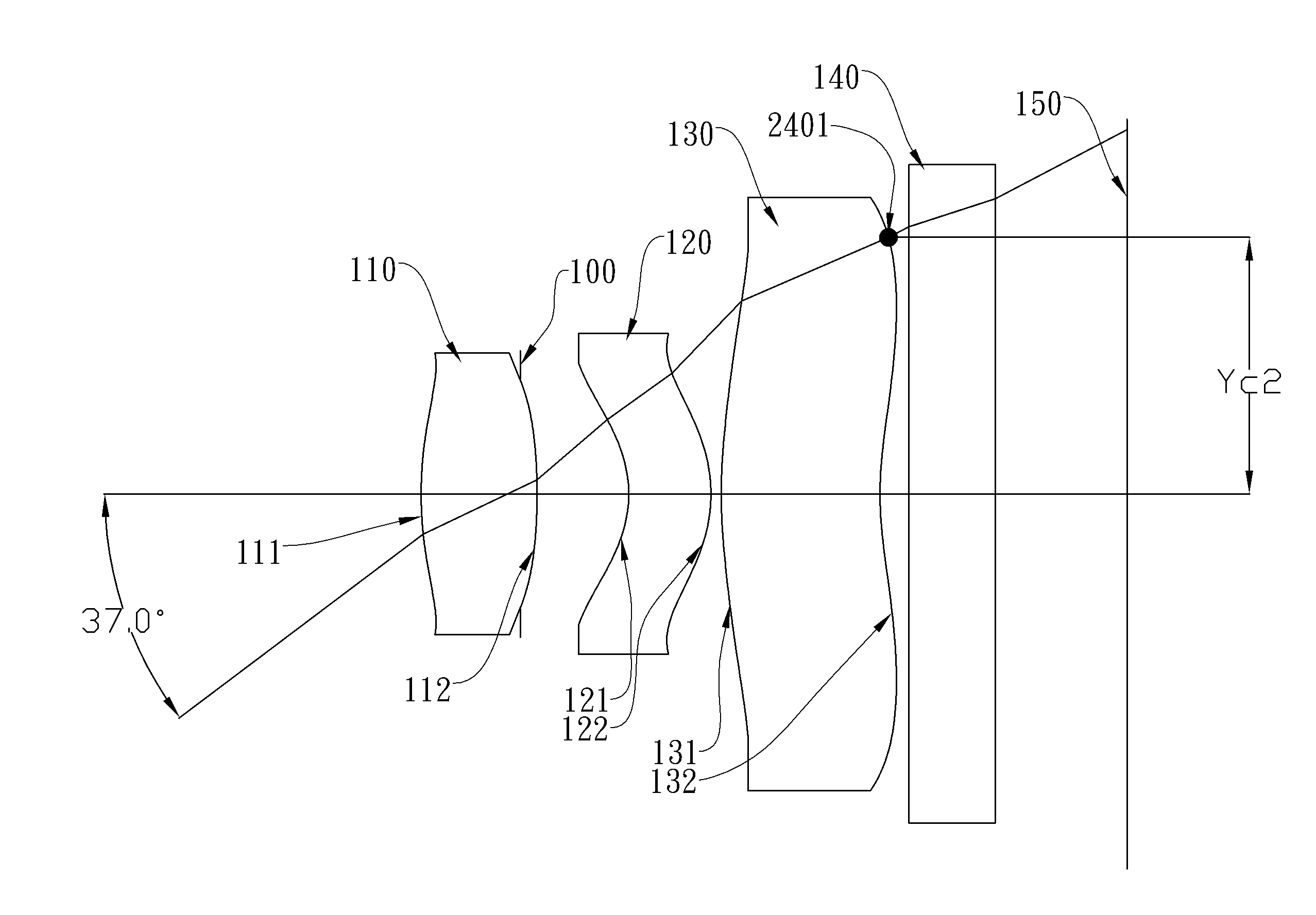
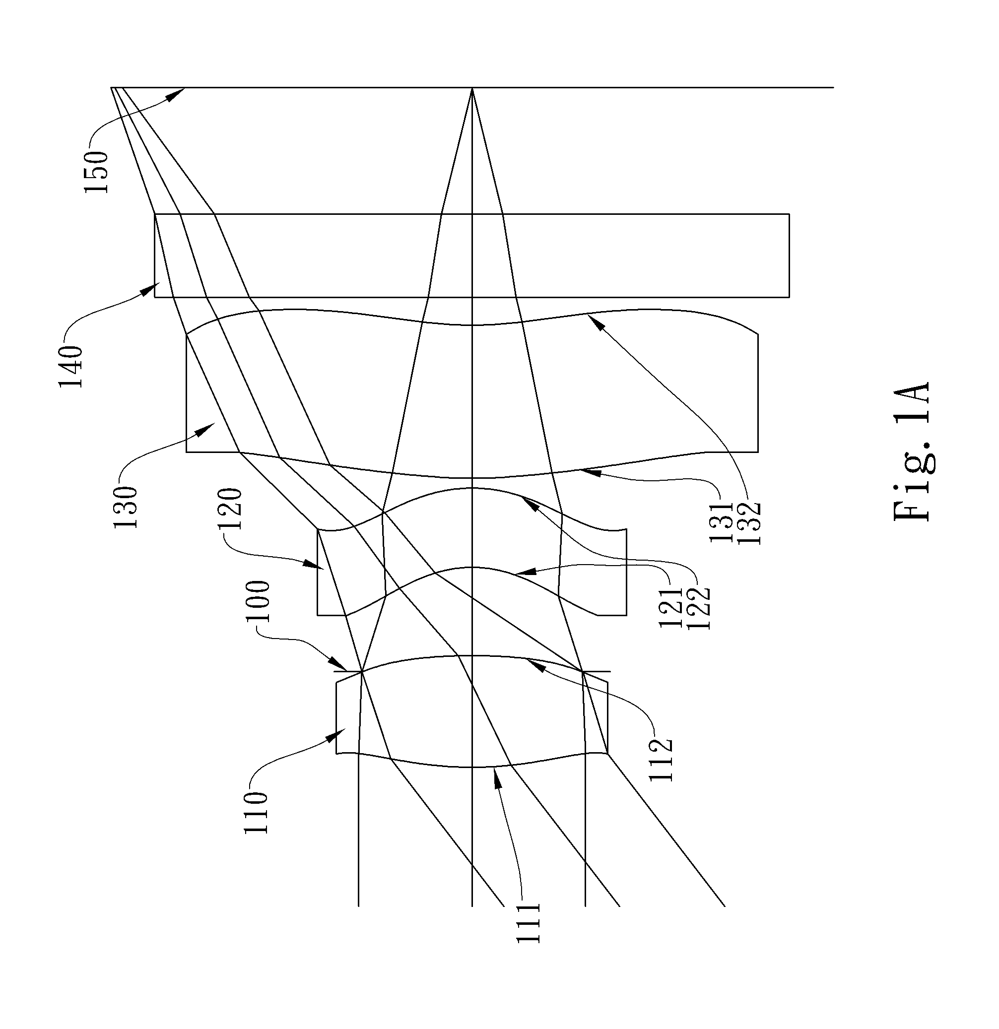
[0064]In the present optical imaging lens assembly, a light ray having an incident angle of 36 degrees relative to the optical axis and passing through a center of the aperture stop intersects to form a point on an image-side surface of the lens element closest to the side of image, the perpendicular distance from the point to the optical axis is Yc1; a light ray having an incident angle of 37 degrees relative to the optical axis and passing through a center of the aperture stop intersects to form a point on an image-side surface of the lens element closest to the side of image, the perpendicular distance from the point to the optical axis is Yc2. The distances and relative locations represented by Yc1 and Yc2 will be further illustrated in FIGS. 23 and 24, respectively. FIGS. 23 and 24 illustrate the optical system of the first embodiment into which light rays having respective incident angles of 36 and 37 degrees are directed. The light ray having an incident angle of 36 degrees r...

second embodiment

[0089]In the present optical imaging lens assembly, the focal length of the optical imaging lens assembly is f, and it satisfies the relation: f=1.90 (mm).

[0090]In the second embodiment of the present optical imaging lens assembly, the f-number of the optical imaging lens assembly is Fno, and it satisfies the relation: Fno=2.40.

[0091]In the second embodiment of the present optical imaging lens assembly, half of the maximal field of view of the optical imaging lens assembly is HFOV, and it satisfies the relation: HFOV=32.5 deg.

[0092]In the second embodiment of the present optical imaging lens assembly, the Abbe number of the first lens element 210 is V1, the Abbe number of the second lens element 220 is V2, and they satisfy the relation: V1−V2=32.5.

[0093]In the second embodiment of the present optical imaging lens assembly, the thickness of the first lens element 210 on the optical axis is CT1, the thickness of the second lens element 220 on the optical axis is CT2, and they satisfy ...

third embodiment

[0102]In the present optical imaging lens assembly, the focal length of the optical imaging lens assembly is f, and it satisfies the relation: f=1.65 (mm).

[0103]In the third embodiment of the present optical imaging lens assembly, the f-number of the optical imaging lens assembly is Fno, and it satisfies the relation: Fno=2.40.

[0104]In the third embodiment of the present optical imaging lens assembly, half of the maximal field of view of the optical imaging lens assembly is HFOV, and it satisfies the relation: HFOV=35.9 deg.

[0105]In the third embodiment of the present optical imaging lens assembly, the Abbe number of the first lens element 310 is V1, the Abbe number of the second lens element 320 is V2, and they satisfy the relation: V1−V2=29.3.

[0106]In the third embodiment of the present optical imaging lens assembly, the thickness of the first lens element 310 on the optical axis is CT1, the thickness of the second lens element 320 on the optical axis is CT2, and they satisfy the ...


PUM


Abstract

The present invention provides an optical imaging lens assembly comprising, in order from an object side to an image side: a first lens element with positive refractive power having a convex object-side surface; a second lens element with negative refractive power having a concave object-side surface; and a third lens element with negative refractive power having a concave image-side surface, at least one of the object-side and image-side surfaces thereof being aspheric. With the aforementioned arrangement of lens elements, the total track length of the optical imaging lens assembly can be effectively reduced, the sensitivity of the optical system can be attenuated, a large field of view can be achieved and the image quality can be improved.

Description

CROSS-REFERENCE TO RELATED PATENT APPLICATION[0001]This non-provisional application claims priority under 35 U.S.C. §119(a) on Taiwanese Patent Application No(s). 099131290 filed in Taiwan, R.O.C., on Sep. 15, 2010, the entire contents of which are hereby incorporated by reference.BACKGROUND OF THE INVENTION[0002]1. Field of the Invention[0003]The present invention relates to an optical imaging lens assembly, and more particularly, to a compact optical imaging lens assembly with a large field of view.[0004]2. Description of the Prior Art[0005]The demand for compact imaging lenses has grown in recent years as the popularity of portable electronic products with the photographing function has increased, and the sensor of a general imaging lens is none other than CCD (Charge Coupled Device) or CMOS (Complementary Metal Oxide Semiconductor Sensor). Furthermore, as advanced semiconductor manufacturing technology has reduced the pixel size of sensors, and the resolution of compact imaging ...

Claims


Application Information

Patent Timeline
Patent Type & Authority Patents(United States)
IPC IPC(8): H04N5/225G02B3/02
CPCG02B13/0035
Inventor TANG, HSIANG CHICHEN, CHUN SHANTSAI, TSUNG HANHUANG, HSIN HSUAN
Owner LARGAN PRECISION
Why Eureka
Try Eureka