

Image capturing lens assembly
a technology of image capturing and lens assembly, which is applied in the field of can solve the problems that the conventional four-piece lens structure cannot meet the requirements of the compact image capturing lens assembly
- Summary
- Abstract
- Description
- Claims
- Application Information
AI Technical Summary
Benefits of technology
Problems solved by technology
Method used
Image

Examples
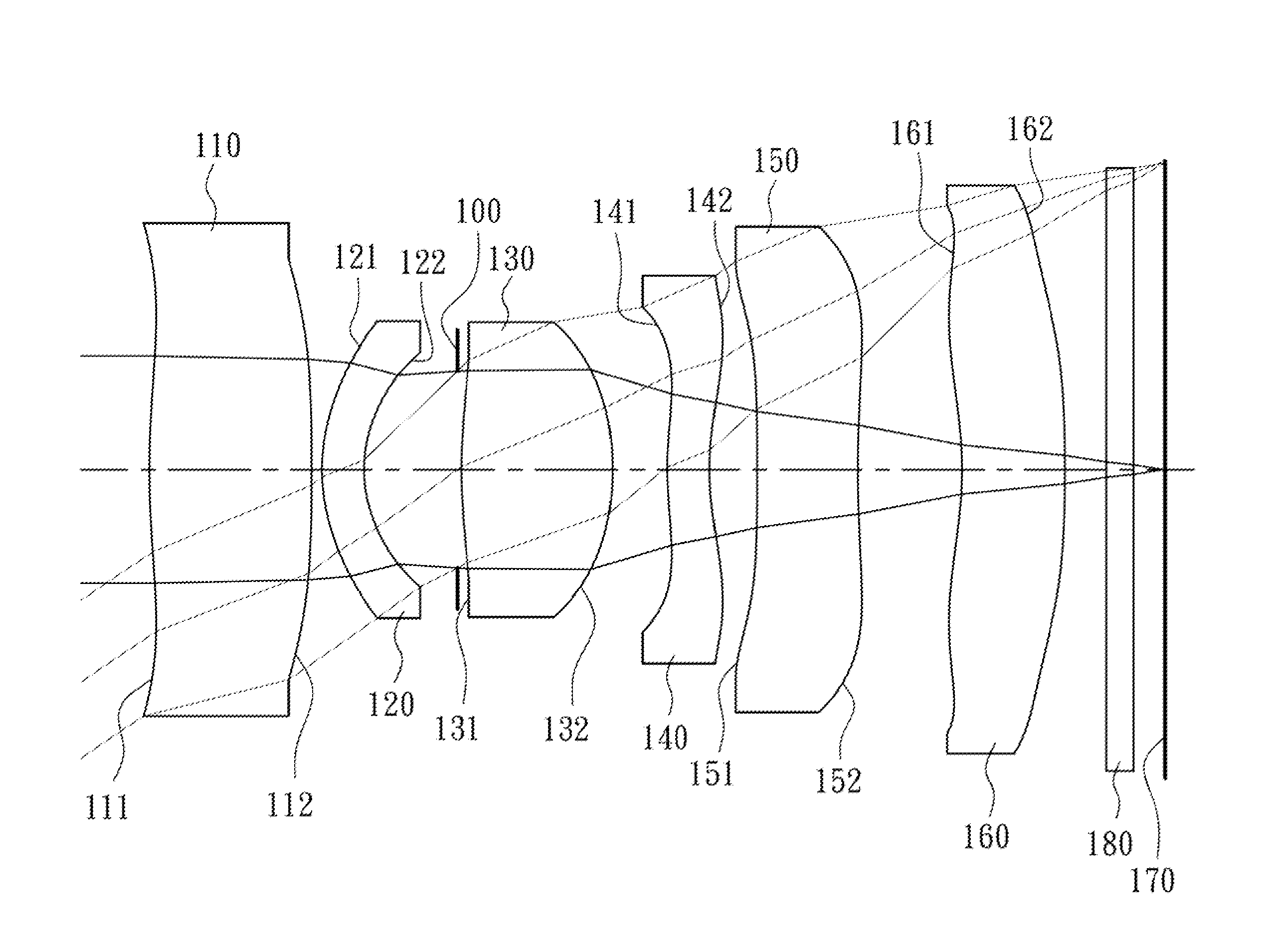
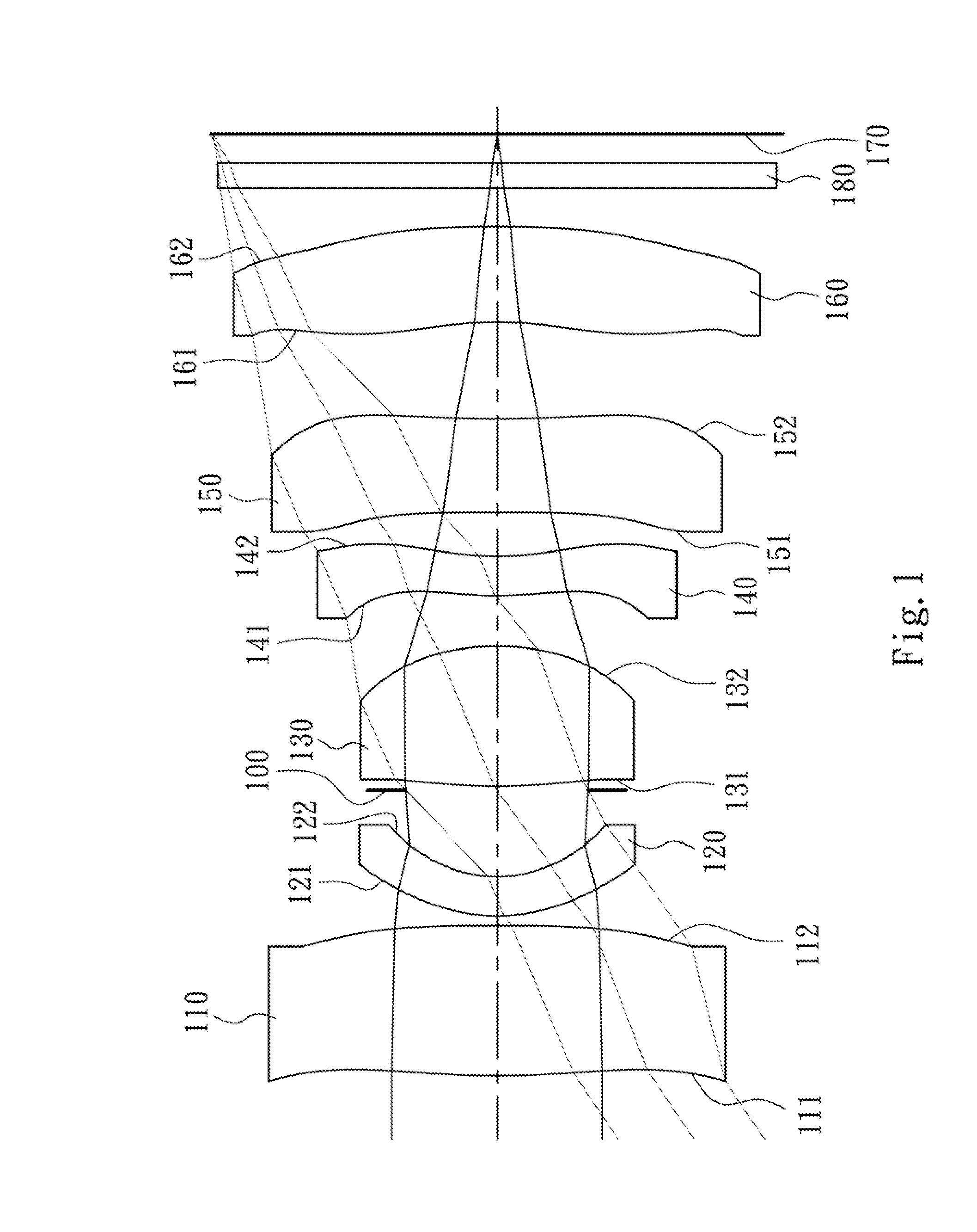
first embodiment
[0075]The equation of the aspheric surface profiles of the aforementioned lens elements of the first embodiment is expressed as follows:
[0076]X(Y)=(Y2 / R) / (1+sqrt(1-(1+k)×(Y / R)2))+∑i(Ai)×(Y2)
[0077]wherein:
[0078]X: the height of a point on the aspheric surface spaced at a distance Y from the optical axis relative to the tangential plane at the aspheric surface vertex;
[0079]Y: the distance from the point on the curve of the aspheric surface to the optical axis;
[0080]k: the conic coefficient; and
[0081]Ai: the i-th aspheric coefficient.
[0082]In the image capturing lens assembly according to the first embodiment, f is a focal length of the image capturing lens assembly, Fno is an f-number of the image capturing lens assembly, HFOV is half of the maximal field of view, and they satisfy the following relationships:
f=5.31 mm;
Fno=3.20; and
HFOV=34.0 degrees.
[0083]In the image capturing lens assembly according to the first embodiment, the Abbe number of the second lens element 120 is V2, the...
second embodiment
[0105]The detailed optical data of the second embodiment are shown in Table 3, and the aspheric surface data are shown in Table 4 as follows.
[0106]
TABLE 32nd Embodimentf = 5.22 mm, Fno = 3.20, HFOV = 37.3 deg.FocalSurface #Curvature RadiusThicknessMaterialIndexAbbe #length0ObjectPlanoInfinity1Lens 14.847100 (ASP)1.213Plastic1.53554.511.64220.000000 (ASP) 0.0703Lens 21.638160 (ASP)0.310Plastic1.61425.5−7.2241.110300 (ASP)0.7915Ape. StopPlano0.0306Lens 33.818000 (ASP)1.235Plastic1.53554.52.547−1.872650 (ASP) 0.2338Lens 43.601300 (ASP)0.335Plastic1.61425.5−6.3391.803750 (ASP)0.37810Lens 514.115300 (ASP) 0.711Plastic1.53554.5−120.641111.377800 (ASP) 0.81912Lens 6−5.109700 (ASP) 0.874Plastic1.53554.5−6.781313.193100 (ASP) 0.30014IR-filterPlano0.200Glass1.51764.2—15Plano0.22516ImagePlano—Note:Reference wavelength (d-line) is 587.6 nm.
[0107]
TABLE 4Aspheric CoefficientsSurface #123467k =0.00000E+000.00000E+001.72069E−01−3.76271E−02−1.18997E−01−3.39293E−01A4 =−2.41424E−02−4.67307E−02−6.62441...
third embodiment
[0119]The detailed optical data of the third embodiment are shown in Table 5, and the aspheric surface data are shown in Table 6 as follows.
[0120]
TABLE 53rd Embodimentf = 5.22 mm, Fno = 3.00, HFOV = 33.5 deg.FocalSurface #Curvature RadiusThicknessMaterialIndexAbbe #length0ObjectPlanoInfinity1Lens 15.668008 (ASP)1.056Plastic1.53556.39.532−47.172124 (ASP) 0.0703Lens 21.506234 (ASP)0.310Plastic1.65021.4−7.7341.064690 (ASP)0.7345Ape. StopPlano0.0306Lens 34.542792 (ASP)1.039Plastic1.53556.32.797−2.045953 (ASP) 0.2888Lens 43.196435 (ASP)0.310Plastic1.61425.6−8.3591.896690 (ASP)0.34210Lens 515.498349 (ASP) 0.770Plastic1.53556.3−58.111110.160607 (ASP) 0.82712Lens 6−2.811467 (ASP) 0.630Plastic1.53556.3−5.5013−68.890140 (ASP) 0.30014IR-filterPlano0.200Glass1.51764.2—15Plano0.22416ImagePlano—Note:Reference wavelength (d-line) is 587.6 nm.
[0121]
TABLE 6Aspheric CoefficientsSurface #123467k =0.00000E+000.00000E+000.00000E+000.00000E+000.00000E+000.00000E+00A4 =−2.64969E−02−4.30098E−02−8.55147E−02...
PUM
 Abstract
Description
Claims
Application Information