Radiation redirecting external case for portable communication device and antenna embedded in battery of portable communication device

a portable communication device and antenna technology, applied in the direction of substantially flat resonant elements, resonant antennas, transmission monitoring, etc., can solve the problems of unnecessary high dielectric constant materials, difficult to achieve in the small space allowed inside the phone case, etc., to increase the effective space for the antenna, increase the available space within the phone casing, and increase the effect of shielding and rf radiation redirection

Active Publication Date: 2012-06-26
PENUMBRA BRANDS LLC
View PDF68 Cites 77 Cited by
  • Summary
  • Abstract
  • Description
  • Claims
  • Application Information

AI Technical Summary

Benefits of technology

[0009]According to a first embodiment, the present invention dramatically increases the effective space for the antenna and provides highly effective shielding and RF radiation redirection away from the user, while actually increasing the available space within the phone casing. The invention incorporates the antenna into the battery such that the antenna lies on the side of the battery facing away from the user, where the battery is attached to the back of the phone facing away from the user. The battery's electrical connections are increased to include all the needed antenna leads into the phone's circuits. All batteries designed for a particular model of phone would feature the antenna built-in.
[0010]One advantage of this design is to afford far more space for the complex antennas of the future, aiding in their optimization. Separate antennas can be employed within the battery, utilizing the relatively larger area available on the battery to provide separation of antennas of different frequencies and functions, thereby reducing interference between the antennas. Another important advantage of this configuration is that it permits optimization of an RF shielding design for wireless phones. The thickness of the battery can serve to provide the needed space between the antenna and a tuned RF shielding element placed within the battery on the side nearest the user, with the lithium ion core or other functional storage medium of the battery lying between the shielding and the antenna. The resulting spacing between the RF shielding and the antenna is optimally one-quarter of the wavelength of the transmission signal. This goal can be aided by the use of a layer of dielectric material between the RF shielding and the antenna, but is still extremely difficult to achieve in the small space allowed inside the phone case. By designing the battery such that the thickness of the battery's storage medium results in the correct spacing for the tuning of the RF shielding, and by grounding the shielding through a connector from the battery to the phone's ground circuit, and by designing the RF shielding itself to optimally redirect the RF radiation away from the user while leaving undiminished the desired signal directed away from the user, a unique benefit of significant reduction in RF absorption by the user's body can be achieved.

Problems solved by technology

This goal can be aided by the use of a layer of dielectric material between the RF shielding and the antenna, but is still extremely difficult to achieve in the small space allowed inside the phone case.
This will make it unnecessary to have a material of high dielectric constant.

Method used


Image

  • Radiation redirecting external case for portable communication device and antenna embedded in battery of portable communication device
  • Radiation redirecting external case for portable communication device and antenna embedded in battery of portable communication device
  • Radiation redirecting external case for portable communication device and antenna embedded in battery of portable communication device

Examples


Embodiment Construction

Antenna Embedded into Battery or Wireless Devices

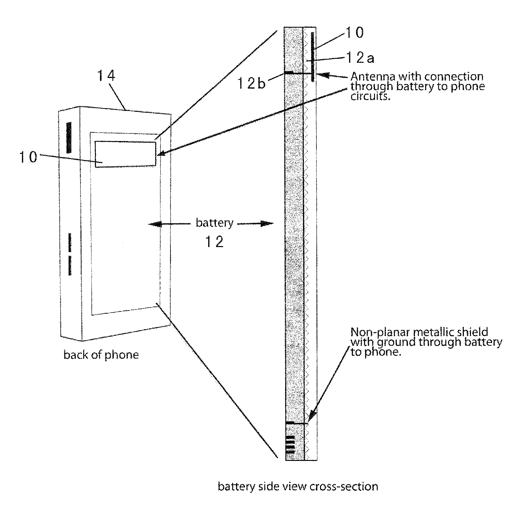
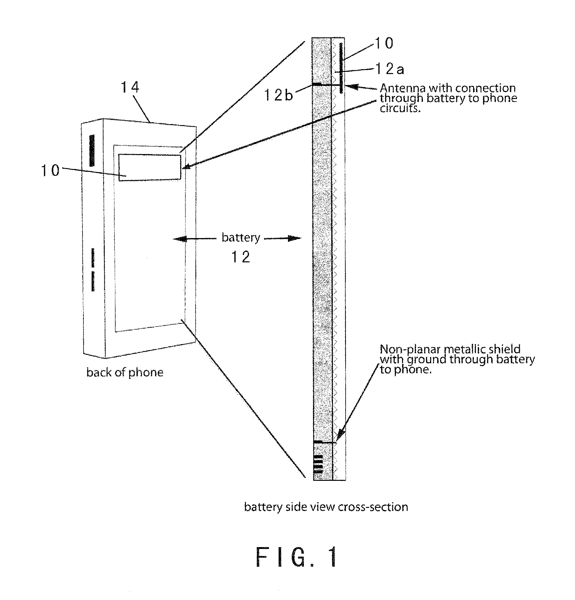
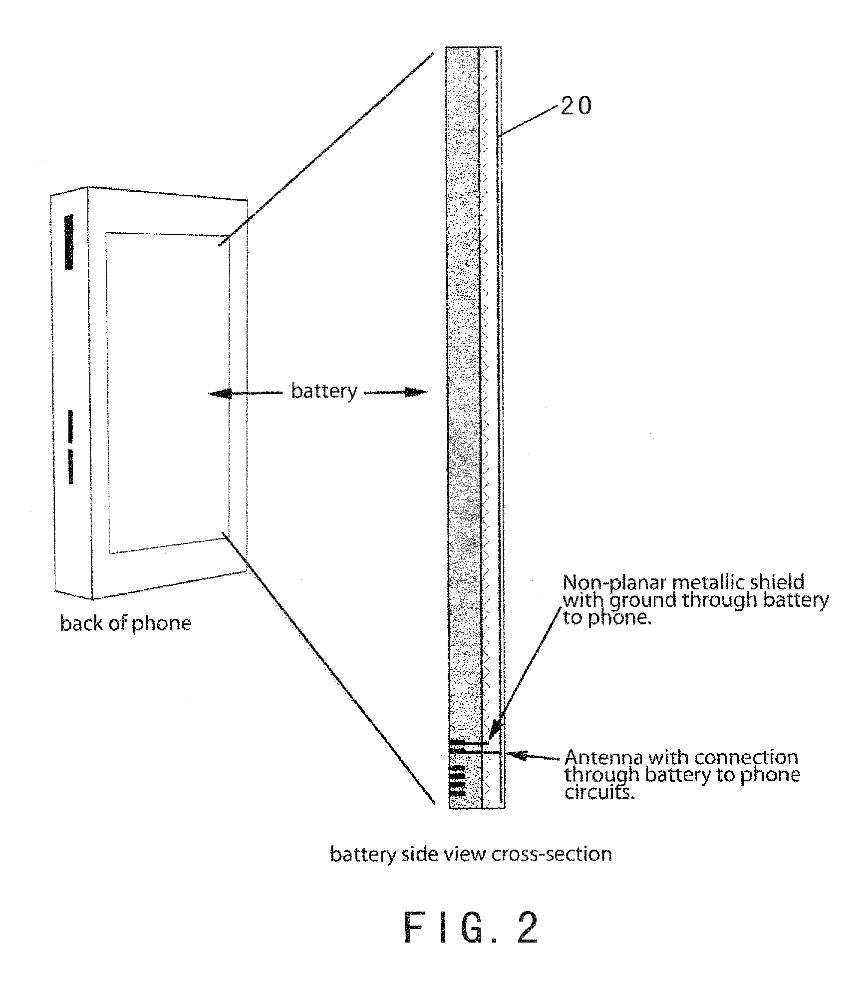
[0027]According to a first aspect of the invention as shown in FIG. 1, an antenna 10 for a wireless device 14 is embedded into the battery 12, such that the space inside the wireless device formerly occupied by the antenna is available for other components, and the antenna is connected to the wireless device's antenna circuit by electrical contact surfaces 12a on the battery casing that contact corresponding surfaces 12b on the phone case, in the same manner as the power connections are made from the battery to the phone's power circuit. The antenna may be of compact design and fitted into one end or side of the battery casing, as shown in FIG. 1. Optionally, the antenna may be made thin and flat and may be placed on the broad flat plane parallel to the battery's energy storage core as shown in FIG. 2 as antenna 20.

[0028]As shown in FIG. 3, separate antennas 30 and 32 of different frequencies may be provided on the battery located apa...


PUM


Abstract

An advanced antenna or set of antennae for a wireless device is provided by embedding the antennae into the battery case or generally the largest surface area of a wireless phone. The antenna connections are made through the battery's connections to the wireless device. The antenna design can be compact and located in any area of the battery. The antenna design can be thin and flat, located at the back surface of the battery or the large rear surface of a wireless phone, facing away from the user. An RF shielding device can be embedded into the battery and configured in relation to the antenna such that the RF field intensity and the consequent specific absorption rate for the user is lowered while the outgoing signals of the wireless device remain fully adequate for the function of the wireless device. This feature is preserved for a multi-band operation because a digital phase shifter is used between two radiating antennae. An external case is used as a complement to the wireless phone to provide additional antennae, power and capability.

Description

CROSS-REFERENCE TO RELATED APPLICATIONS AND CLAIM FOR PRIORITY[0001]This application claims benefit under 35 U.S.C. §119(e) of provisional application Ser. No. 61 / 112,141 filed Nov. 6, 2008, and provisional application Ser. No. 61 / 158,551 filed Mar. 9, 2009, the entire contents of which are incorporated herein by reference in their entirety.BACKGROUND OF THE INVENTION[0002]1. Field of the Invention[0003]This invention relates generally to portable communication devices such as cell phones, smart phones and similar handheld devices, and improvements thereto. In particular, this invention provides improvements in antennas and RF shielding of such devices, the embedding of an antenna into the removable battery of a portable communication device, or any large surface area inside a phone, facing a direction away from the user, to redirecting RF radiation away from the body of a user, and to several methods of exploiting technical advantages that result from embedding an antenna into the ...

Claims


Application Information

Patent Timeline
Patent Type & Authority Patents(United States)
IPC IPC(8): H04M1/00
CPCH01Q1/243H01Q1/245H01Q1/48H01Q9/0407H01Q5/371H04B1/3838H04B1/3883H05K9/0056H01Q15/14
Inventor WONG, ALFRED Y.MORENO, ROBERTSHIELDS, KARL RICHARDWANG, RONG
Owner PENUMBRA BRANDS LLC
Why Eureka
Try Eureka