Connecting device between tank and pump

A technology of connectors and connecting parts, which is applied in the direction of valve details, valve devices, valve housing structures, etc., can solve the problems of large space occupation and complicated installation, and achieve the effect of small space occupation, increased effective space and small installation size

Active Publication Date: 2016-03-02
BC P INC CHINA NAT PETROLEUM CORP +1
View PDF7 Cites 5 Cited by
  • Summary
  • Abstract
  • Description
  • Claims
  • Application Information

AI Technical Summary

Problems solved by technology

[0004] In order to overcome the problems of complex installation and large space occupation of existing pumps, the present invention provides a connector between the tank and the pump. The connector itself has a small vertical installation size, which not only increases the effective space of the tank but also facilitates overhaul

Method used


Image

  • Connecting device between tank and pump
  • Connecting device between tank and pump

Examples


Embodiment 1

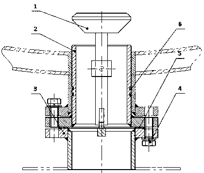
[0024] In order to overcome the problems of complex installation and large space occupation of existing pumps, the present invention provides such figure 1 , figure 2 The connector between the tank and the pump shown is small in vertical installation size, which not only increases the effective space of the tank but also facilitates the maintenance of the pump.

[0025] A connector between a tank and a pump, including a valve core 1 and a valve seat 2, the lower end of the valve seat 2 is covered with a pump feed port connector 3, the valve core 1 is composed of a valve shoe 1.1, a valve stem 1.2, and a valve head 1.3 Composition, the lower end of valve stem 1.2 is connected with valve shoe 1.1, the upper end of valve stem 1.2 is connected with valve head 1.3; On the support plate 3.2 provided at the upper end of the pump inlet connector 3.

[0026] It includes at least a valve core 1, a valve seat 2, and a pump feed port connector 3; the valve core 1 and valve seat 2 are i...

Embodiment 2

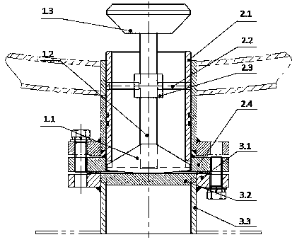
[0029] Based on the basis of Embodiment 1, in this embodiment, the valve core 1 is composed of a valve shoe 1.1, a valve stem 1.2, and a valve head 1.3. The bottom of 1.1 is a reverse arch, and the valve head 1.3 is a truncated cone.

[0030] The valve head 1.3 in the valve core 1 is a truncated cone and can play a sealing role when the upper end surface of the valve seat cylinder 2.1 in the valve seat 2 is fitted; the lower end surface of the valve seat cylinder 2.1 in the valve seat 2 has a gap , the valve shoe 1.1 in the spool 1 snaps into the gap after the pump inlet connector 3 is installed in place.

[0031] The valve stem 1.2 in the valve core 1 is in sliding fit with the sliding sleeve 2.3 in the valve seat 2.

[0032] The valve seat 2 is composed of a valve seat cylinder 2.1, a sliding sleeve fixing rod 2.2, a sliding sleeve 2.3, and a valve seat flange 2.4. The valve seat cylinder 2.1 and the sliding sleeve 2.3 are connected through the sliding sleeve fixing rod 2.2...


PUM


Abstract

The invention provides a connecting device between a tank and a pump. The connecting device comprises a valve element and a valve seat. The lower end of the valve seat is sleeved with a pump material inlet connecting member. The valve element is composed of a valve shoe, a valve rod and a valve head. The lower end of the valve rod is connected with the valve shoe. The upper end of the valve rod is connected with the valve head. The valve head is located outside the upper end of the valve seat. The valve rod and the valve shoe are located in the valve seat. The valve shoe is supported on a supporting plate arranged at the upper end of the pump material inlet connecting member. The bottom of the valve shoe is in an inverted-arch shape. The valve head is a circular truncated cone. The valve seat is composed of a valve seat barrel, sliding sleeve fixing poles, a sliding sleeve and a valve seat flange. The valve seat barrel is connected with the sliding sleeve through the sliding sleeve fixing poles. A notch is formed in the lower end face of the valve seat barrel. The pump material inlet connecting member is composed of a flange and a welding barrel. When the pump material inlet connecting member is connected to the lower portion of the valve seat, the valve element moves upwards and a flow pass is opened; when the pump material inlet connecting member is moved away from the lower portion of the valve seat, the valve element moves downwards and the flow pass is closed. The connecting device has the characteristics of being convenient to install, small in occupied size and visual and reliable in blocking.

Description

technical field [0001] The invention relates to a viscous material conveying connection device, in particular to a connector between a tank and a pump. Background technique [0002] During material transportation, in order to facilitate the maintenance of the pump, a connecting valve and a telescopic short joint are generally provided between the pump and its upper supply tank. Install directly. [0003] However, the main problem of the above-mentioned technology is: in the case of the overall height limitation of the skid-mounted equipment, if the existing valve and telescopic short-circuit connection method is directly used, the vertical dimension will be relatively large, which will reduce the size of the premix tank. effective space. A connector between the tank and the pump has been designed for this purpose. Contents of the invention [0004] In order to overcome the problems of complex installation and large space occupation of existing pumps, the present inventi...

Claims


Application Information

Patent Timeline
Patent Type & Authority Applications(China)
IPC IPC(8): F16K27/02F16K1/32
CPCF16K1/32F16K27/02F16K27/0254
Inventor 王玉李前春胡东锋张毓民王思凡张新发吴光徐军谭欢
Owner BC P INC CHINA NAT PETROLEUM CORP
Why Eureka
Try Eureka