

Electrical terminal
a technology of electric terminals and terminals, applied in the direction of contact members penetrating/cutting insulation/cable strands, coupling bases/cases, electrical devices, etc., can solve the problem of limiting the maximum possible rotation or tilting of the actuating element, and achieves small installation size, good and reliable handling, and simple structure
- Summary
- Abstract
- Description
- Claims
- Application Information
AI Technical Summary
Benefits of technology
Problems solved by technology
Method used
Image

Examples
Embodiment Construction
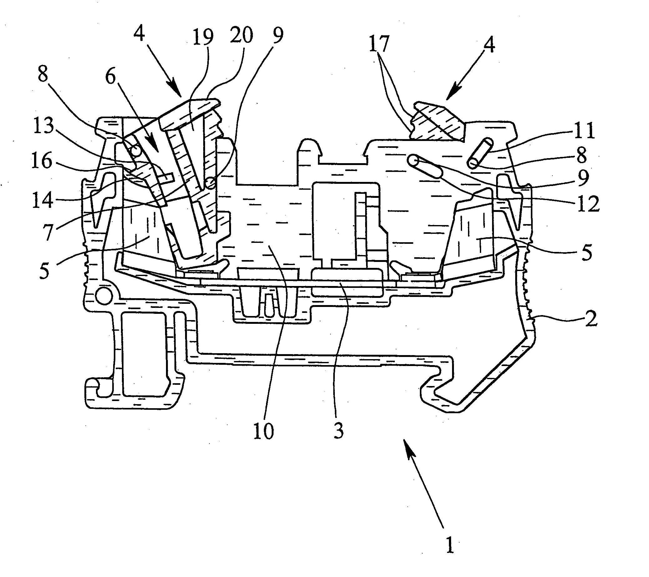
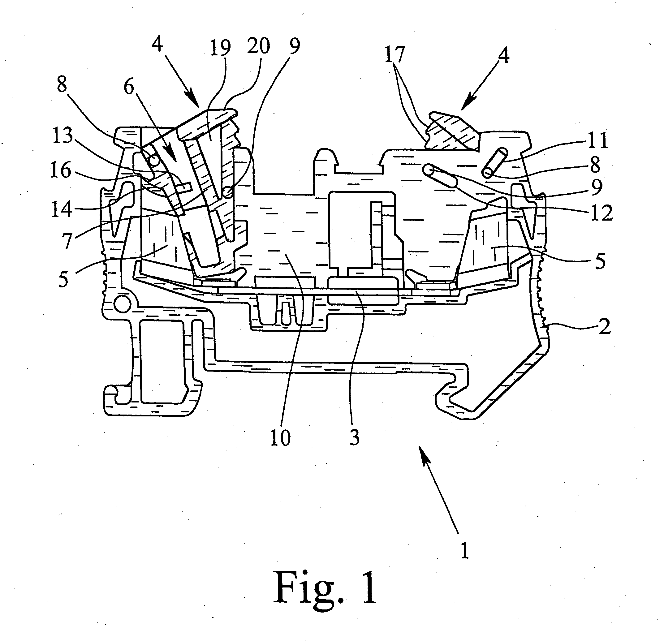
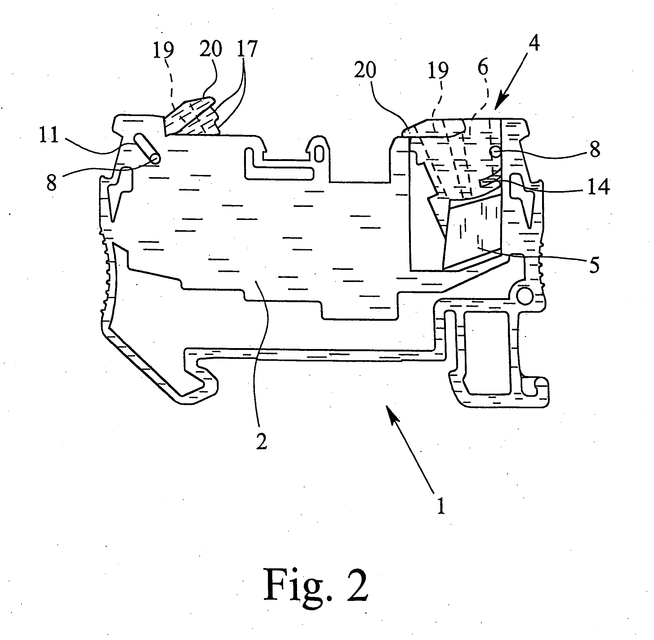
[0019] The electrical terminal 1 shown in FIGS. 1 & 2 has a housing 2. In the figures, a connecting terminal for two conductors which are to be connected is shown. It goes without saying that the electrical terminal as provided by the present invention can also be made as a three-conductor or four-conductor connecting terminal. In the housing 2 of the electrical terminal 1, there is a busbar 3 and two actuating elements 4. In addition, the electrical terminal 1 has two insulation piercing elements 5 which are each connected to one another in an electrically conductive manner by the busbar 3.
[0020] The actuating elements 4 which each have one conductor receiver 6 for the conductors which are to be connected (not shown) are arranged to be able to turn relative to the insulation piercing elements 5 in the housing 2 of the electrical terminal 1 so that the actuating elements 4 can be pivoted out of a first position in which the insertion of an incoming conductor into the conductor rece...
PUM
 Abstract
Description
Claims
Application Information