Lock ring type synchronizer and synchronizing method thereof

A synchronizer and lock ring technology, applied in clutches, mechanical drive clutches, mechanical equipment, etc., can solve the problems of large synchronizer installation size, small synchronizer capacity, complex structure, etc., achieve easy vehicle layout, improve synchronizer The effect of life and overall compact structure

Inactive Publication Date: 2014-09-10
SHAANXI FAST AUTO DRIVE GROUP CO LTD
View PDF4 Cites 7 Cited by
  • Summary
  • Abstract
  • Description
  • Claims
  • Application Information

AI Technical Summary

Problems solved by technology

[0007] The purpose of the present invention is to overcome the defects of the prior art, and provide a lock-ring synchronizer and its synchronization method to solve the problems of large installation size, complex structure and small capacity of the existing synchronizer

Method used


Image

  • Lock ring type synchronizer and synchronizing method thereof
  • Lock ring type synchronizer and synchronizing method thereof
  • Lock ring type synchronizer and synchronizing method thereof

Examples


Embodiment Construction

[0032] The present invention will be described in detail below in conjunction with the accompanying drawings.

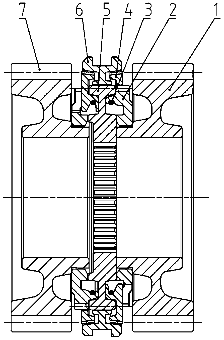
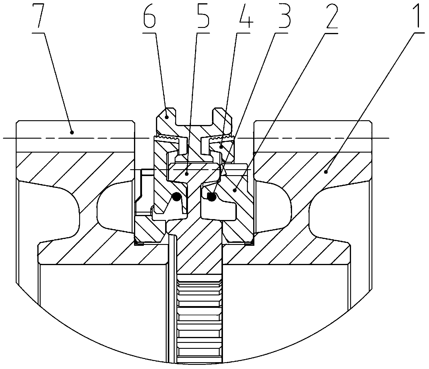
[0033] The locking ring type synchronizer of the present invention comprises gear hub 5, sliding sleeve 6, return spring 3, synchronizing cone ring 4 and combined ring gear 2; the inner diameter of gear hub 5 is provided with an inner spline connected with an outer spline on the shaft, The outer diameter of the gear hub 5 is provided with external splines; the sliding sleeve 6 is set on the gear hub 5, and the inner wall of the sliding sleeve 6 is provided with internal splines meshing with the outer splines of the gear hub 5, and the inner splines on the side of the sliding sleeve 6 There is a friction cone on the inner circle; figure 1 As shown, the synchronous cone ring 4 is located on one side of the gear hub 1 and the sliding sleeve 6, and the outer circle of the synchronous cone ring 4 is provided with a friction cone surface, and is partially or completely sle...


PUM


Abstract

The invention provides a lock ring type synchronizer and a synchronizing method thereof. The synchronizer comprises gear hubs, slide sleeves, return springs, synchronous conical rings and jointed gear rings. The slide sleeves sleeve the gear hubs, the inner walls of the synchronous conical rings are provided with a plurality of locking bosses uniformly distributed, each locking boss is provided with a first locking slope, the side walls of the jointed gear rings are provided with annular bosses extending axially, the annular bosses are provided with locking grooves matched with the locking bosses on the inner walls of the synchronous conical rings, the locking grooves are provided with second locking slopes, the slide sleeves slide from one sides of the gear hubs to the jointed gear rings so as to push the synchronous conical rings and the jointed gear rings to be matched, and the synchronous conical rings are driven to overpass the jointed gear rings by the return springs, so that internal splines of the slide sleeves are meshed with outer splines of the jointed gear rings. The lock ring type synchronizer is compact in integral structure and small in axial size, and has larger friction radius than that of conventional lock ring synchronizers due to the fact that the slide sleeves are provided with frictional conical surfaces, that is, larger capacity of the synchronizer is achieved, and a transmission is higher in operation comfortableness and reliability and lower in cost.

Description

technical field [0001] The invention belongs to the field of automobiles and relates to a ring-lock synchronizer and a synchronization method thereof. Background technique [0002] With the rapid development of the domestic automobile industry, heavy truck customers have also begun to have higher and higher requirements for the size, weight and handling comfort of the transmission, among which the synchronizer is one of the important factors affecting the size, weight and handling comfort of the transmission , is a key component of the transmission. There is still a certain gap between the existing domestic synchronizers and foreign technologies, which is mainly reflected in two aspects: the life of the synchronizer and the feel of the synchronizer in gear. [0003] Problems with existing synchronizers: [0004] A. The installation size of the synchronizer is large; with the development of transmission technology, customers have higher and higher requirements for the size ...

Claims


Application Information

Patent Timeline
Patent Type & Authority Applications(China)
IPC IPC(8): F16D23/04
Inventor 张国英强革涛王魏
Owner SHAANXI FAST AUTO DRIVE GROUP CO LTD
Why Eureka
Try Eureka