Cylindrical milling rotor with quick grading and working method thereof

A milling and rotor technology, applied in grain processing, etc., can solve problems such as easy agglomeration, wall sticking, low classification efficiency, excessive power consumption, etc., and achieve the effects of eliminating slow circulation, improving milling efficiency, and increasing effective space

Active Publication Date: 2018-11-13
赵东生
View PDF10 Cites 5 Cited by
  • Summary
  • Abstract
  • Description
  • Claims
  • Application Information

AI Technical Summary

Problems solved by technology

[0005] The purpose of the present invention is to provide a cylindrical milling rotor capable of rapid classification, which can not only expand the distribution of hammer blades along the axial direction of the milling rotor, but also make the material particles be ground and transported in the expanded milling area, and solve the problem of material formation. Circulation, the problem of excessive power consumption, can also quickly and efficiently separate the coarse particle materials separated by the grading impeller from the grading area, and return to the milling area for circulation and regrinding, so as to solve the problem of slow material reflux, easy agglomeration, and sticking to the wall. Inability to recirculate quickly, resulting in low classification efficiency

Method used


Image

  • Cylindrical milling rotor with quick grading and working method thereof
  • Cylindrical milling rotor with quick grading and working method thereof
  • Cylindrical milling rotor with quick grading and working method thereof

Examples


Embodiment Construction

[0030] In order to make the purpose, technical solutions and advantages of the embodiments of the present invention more clear, the technical solutions in the embodiments of the present invention will be clearly and completely described below in conjunction with the embodiments of the present invention and the accompanying drawings.

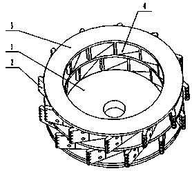
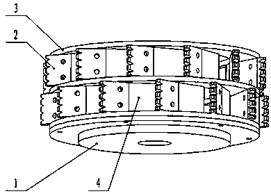
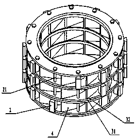
[0031] figure 1 , figure 2 It is a structural schematic diagram of a specific embodiment 1 of the present invention. In the embodiment, the power disc 1 is threaded and image 3 The grinding cylinder connection, image 3 The grinding cylinder is welded together by three ring-shaped shell parts (3) through two sets of blade-shaped centrifugal guide parts (4), and the centrifugal guide parts (4) are uniform around the axis of the ring-shaped shell part (3). Distribution, between the two annular shell parts (3), the evenly distributed return channel is divided by the centrifugal guide part (4), the hammer knife (2) is connected to the centrifugal...


PUM


Abstract

The invention discloses a cylindrical milling rotor with quick grading and a working method thereof. The cylindrical milling rotor comprises powering discs, hammer cutting tools and a cylindrical milling cylinder. The milling cylinder is at least composed of annular shell parts and centrifugation guide parts. The centrifugation guide parts play a role of guiding and backflowing to materials. The annular shell parts are distributed in the axial direction of the milling cylinder. The centrifugation guide parts are arranged between the annular shell parts in the circumferential direction of the milling cylinder. A backflow channel of coarse particles is arranged between the annular shell parts. During working hours, the cylindrical milling rotor rotates at a high speed and forms a high centrifugal field, the coarse particles separated by grading impellers are captured by the centrifugal field generated by rotation of the cylindrical milling rotor, and the coarse particles return to a milling area through the backflow channel. The coarse particles are separated quickly and efficiently, fine particles are sorted efficiently and accurately, and grading efficiency is improved.

Description

technical field [0001] The invention relates to the field of pulverizers, in particular to a cylindrical pulverizing rotor capable of rapid classification and a working method thereof. Background technique [0002] The milling rotors of the milling machines in the prior art are mostly disc-shaped, such as the milling machines with the application number 2015206070065, the application number 201320861999X, and the application number 2015210542529; The ring gear, the grading impeller, and the static material guide sleeve set outside the grading impeller, when working, the grinding disc drives the hammer knife to rotate at a high speed, and the material is ground in the grinding area composed of the hammer knife and the ring gear. Under the action of the wind, it enters the classification area composed of the classification impeller and the material guide sleeve for classification. The classification impeller rotates at a high speed, and the tangential velocity of the airflow b...

Claims


Application Information

Patent Timeline
Patent Type & Authority Applications(China)
IPC IPC(8): B02C13/28
CPCB02C13/2804
Inventor 赵东生
Owner 赵东生
Why Eureka
Try Eureka