High velocity microbot

Inactive Publication Date: 2012-07-03
THE UNITED STATES OF AMERICA AS REPRESENTED BY THE SECRETARY OF THE NAVY
View PDF14 Cites 51 Cited by
  • Summary
  • Abstract
  • Description
  • Claims
  • Application Information

AI Technical Summary

Benefits of technology

[0006]A high velocity microbot and methods for use therefor in accordance with several embodiments of the invention includes a spherical housing, a means for locomotion of the microbot in the horizontal plane that is located internal to the housing, and a plunger that oriented to selectively extend in the vertical direction. In some embodiments, the plunger strikes the interior surface of the housing when it extends to cause motion of th

Problems solved by technology

Since the traction ball is frictionally engaged with the interior surface of the housing, rotation of the ball fu

Method used


Image

  • High velocity microbot
  • High velocity microbot
  • High velocity microbot

Examples


Embodiment Construction

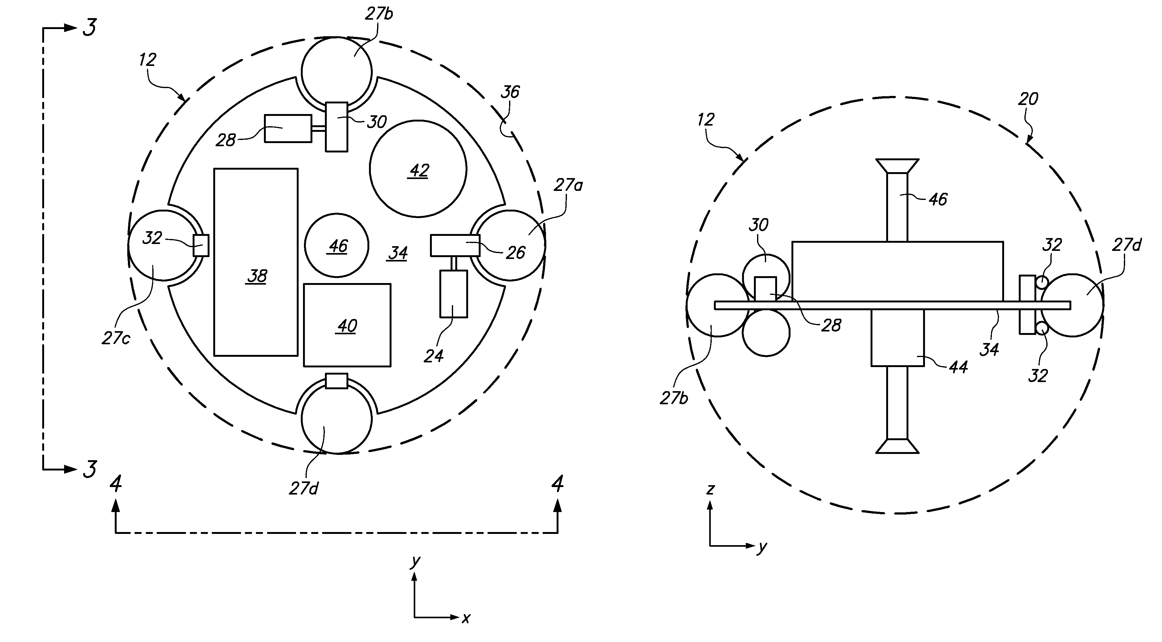
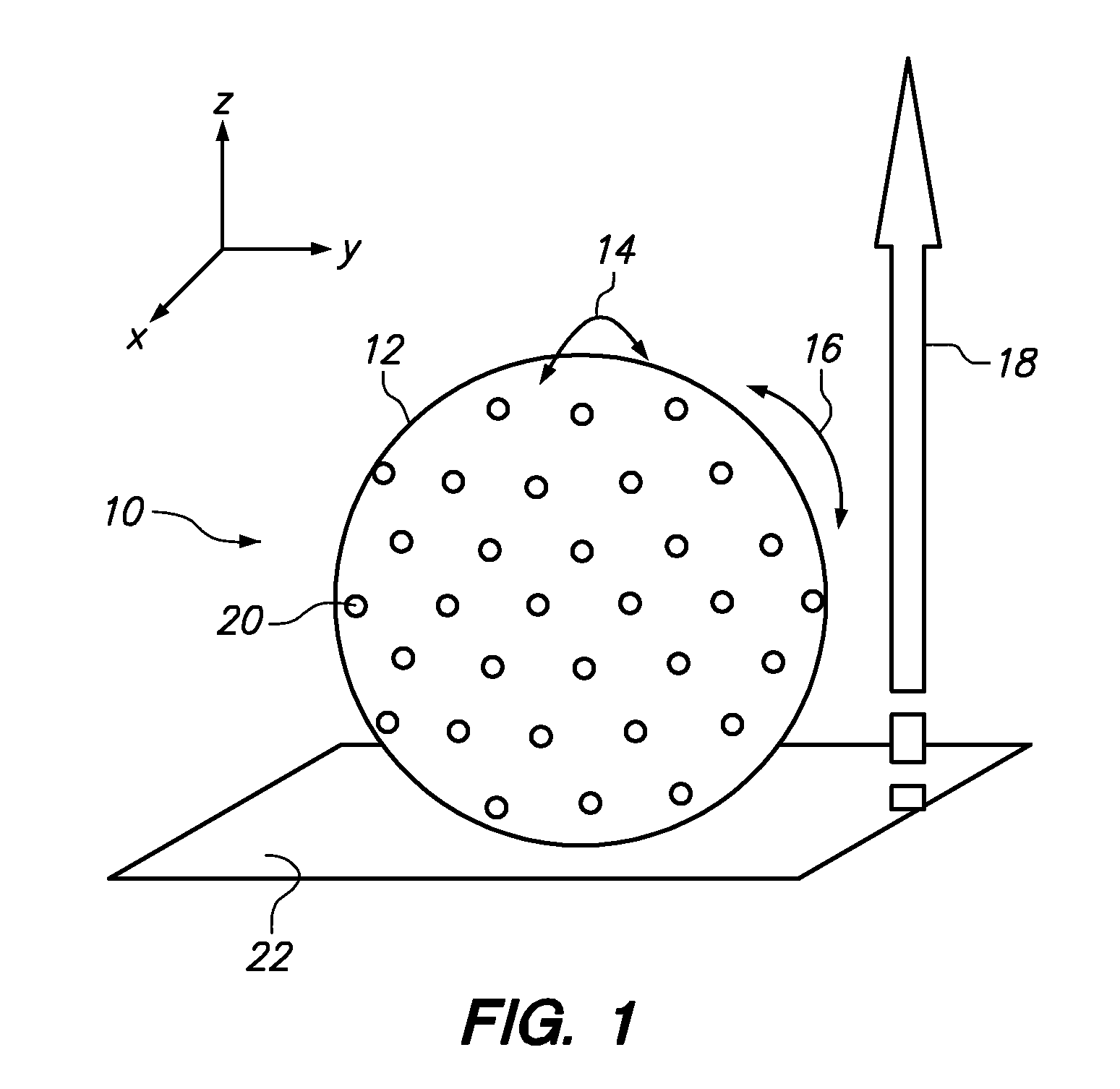
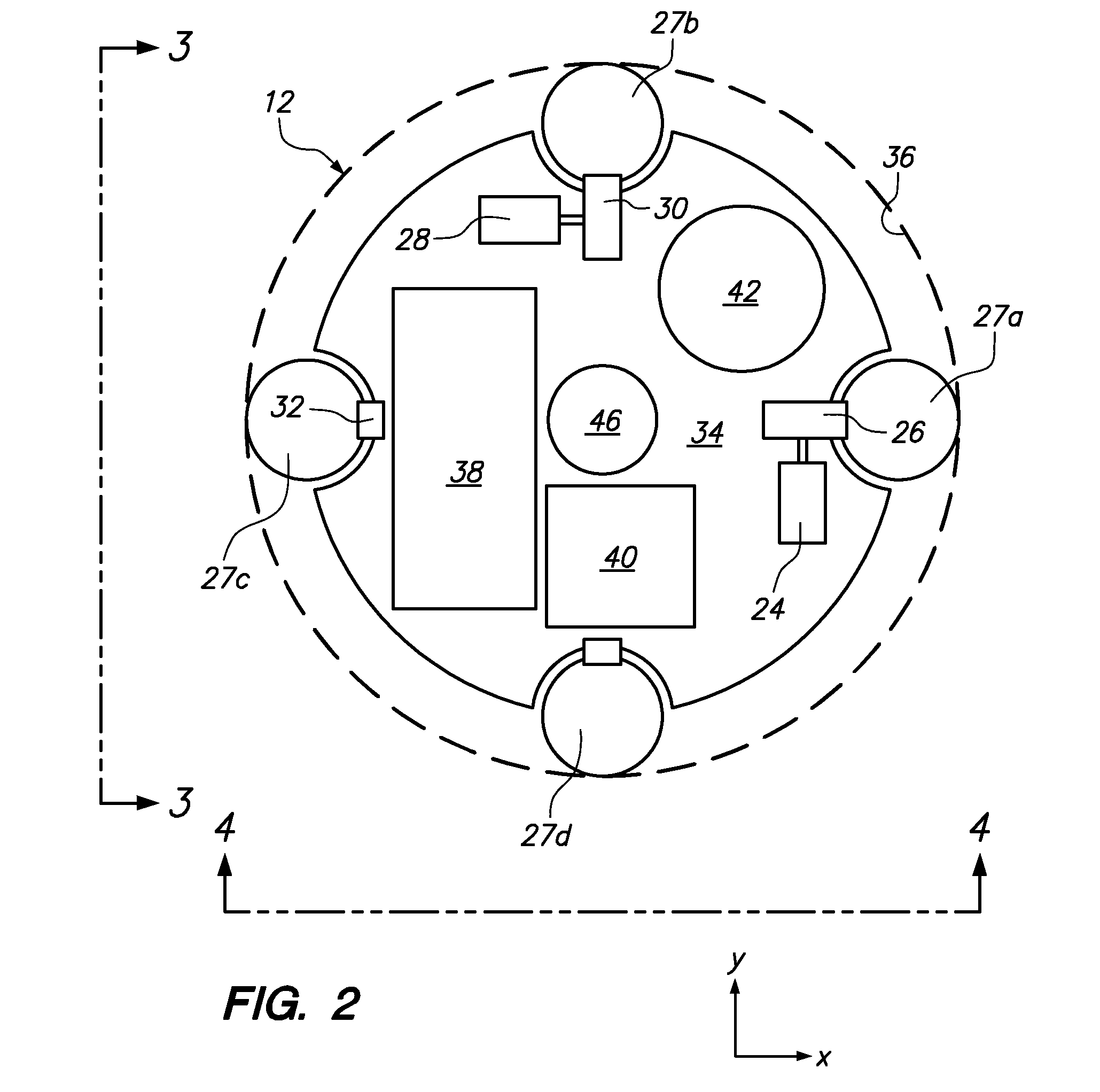
[0017]Referring initially to FIG. 1, a high velocity microbot according to several embodiments of the present invention is shown and is generally designated by reference character 10. As shown, microbot 10 includes a spherical housing 12, which allows for translation in the x-direction and y-direction in a rolling motion along the horizontal plane 22, as indicated by arrows 14 and 16, respectively. The microbot further includes a plunger to accomplish locomotion in the z-direction (arrow 18) via a hopping action. The plunger and the manner in which motion in the z direction is accomplished will be described in further detail below.

[0018]In some embodiments, the spherical housing 12 can have a diameter of about 2 to 3 inches that will be constructed out of about one millimeter (1 mm) thick polycarbonate, although other diameters, thicknesses and materials may be employed. For example, if heavier / larger payloads are desired, if may be desirable to have a microbot with a housing 12 tha...


PUM


Abstract

A microbot includes a spherical housing, first and second servomotors that are located internal to the housing and oriented horizontally and orthogonal to each other, and a plunger within the housing that selectively extends in the vertical direction. Castors are attached to each servomotor; and traction balls corresponding to each castor are placed so that each ball frictionally engages both a respective castor and the interior of the housing at the same time. As the servomotors rotate, the attached castors also rotate, which causes rotation of the traction balls and rolling of the housing, and results in translation of the microbot in the horizontal plane. As the plunger rapidly extends, it strikes the interior surface of the housing with sufficient force to cause a hopping motion of the microbot in the vertical direction.

Description

FEDERALLY-SPONSORED RESEARCH AND DEVELOPMENT[0001]This invention (Navy Case No. 099706) is assigned to the United States Government and is available for licensing for commercial purposes. Licensing and technical inquiries may be directed to the Office of Research and Technical Applications, Space and Naval Warfare Systems Center, Pacific, Code 2112, San Diego, Calif., 92152; voice 619-553-2778; email T2@spawar.navy.mil.FIELD OF THE INVENTION[0002]This disclosure relates generally to robotics. More specifically, this disclosure relates to robots that can move at a high rate of velocity, while at the same time being able to perform high level robot functions and having a particularly small size.BACKGROUND OF THE INVENTION[0003]There is currently a lot of interest in autonomous micro-robots, or microbots, which has arisen due to the advances in micro-electromechanical systems (MEMS) and nano-electromechanical systems (NEMS) manufacturing techniques. Microbots can incorporate many capab...

Claims


Application Information

Patent Timeline
IPC IPC(8): B62D57/00
CPCB62D57/02
Inventor LU, RYAN P.RAMIREZ, AYAX D.RUSSELL, STEPHEN D.
Owner THE UNITED STATES OF AMERICA AS REPRESENTED BY THE SECRETARY OF THE NAVY
Why Eureka
Try Eureka