Gangable modular electrical box assembly with interlocking modules

a modular, electrical box technology, applied in the direction of machine supports, electrical apparatus casings/cabinets/drawers, coupling device connections, etc., can solve the problems of difficult child-proofing, high labor intensity, and many devices that cannot be easily assembled and configured by a single electrician or homeowner, so as to facilitate and quickly assembled, minimize production costs, and quickly configure

Active Publication Date: 2012-07-03
ARLINGTON INDS
View PDF14 Cites 18 Cited by
  • Summary
  • Abstract
  • Description
  • Claims
  • Application Information

AI Technical Summary

Benefits of technology

[0006]A first object of the gangable modular electrical box of the present invention is to provide modular components that can be easily and rapidly assembled at the job site by a single installer to create a multi-gang electrical box.
[0007]A second object of the gangable modular electrical box of the present invention is to provide an installer the ability to rapidly configure a two-gang, three-gang, or even larger multi-gang electrical box in a modular fashion.
[0008]A third object is to provide modular members that are molded of plastic in a single piece to minimize production cost.
[0009]A further object is to provide modular plastic components that include an alignment and connection arrangement is included on the various modules to facilitate easy assembly of the modules at the job site without the use of sophisticated tools.
[0010]Another object of the present invention is to provide modular components in which an alignment and connection arrangement enables the modules to be snapped together and remain connected initially until permanently fastened together.
[0011]These and other objects and advantages of the present invention will be better understood by reading the following description along with reference to the drawings.

Problems solved by technology

Although outlets can be provided by power strips, these devices are likely to be unsightly and difficult to child-proof as compared to outlets installed in the wall.
Although several multi-gang boxes have been proposed, many of them cannot be easily assembled and configured by a single electrician or homeowner.

Method used


Image

  • Gangable modular electrical box assembly with interlocking modules
  • Gangable modular electrical box assembly with interlocking modules
  • Gangable modular electrical box assembly with interlocking modules

Examples


second embodiment

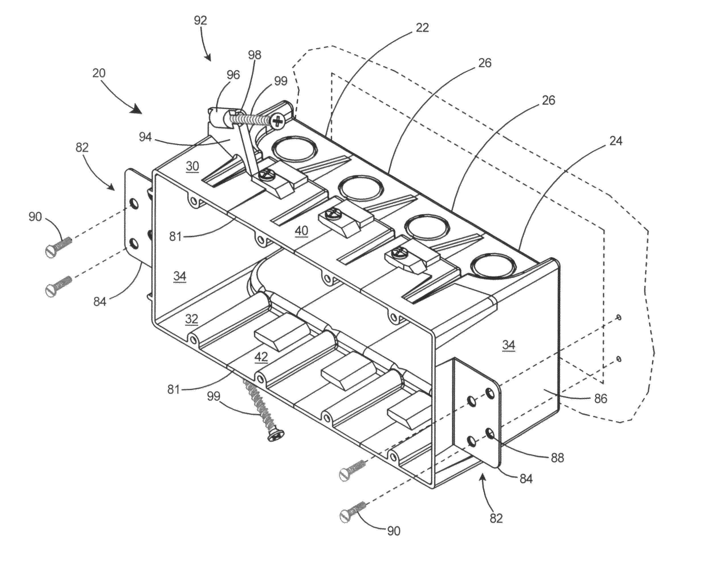
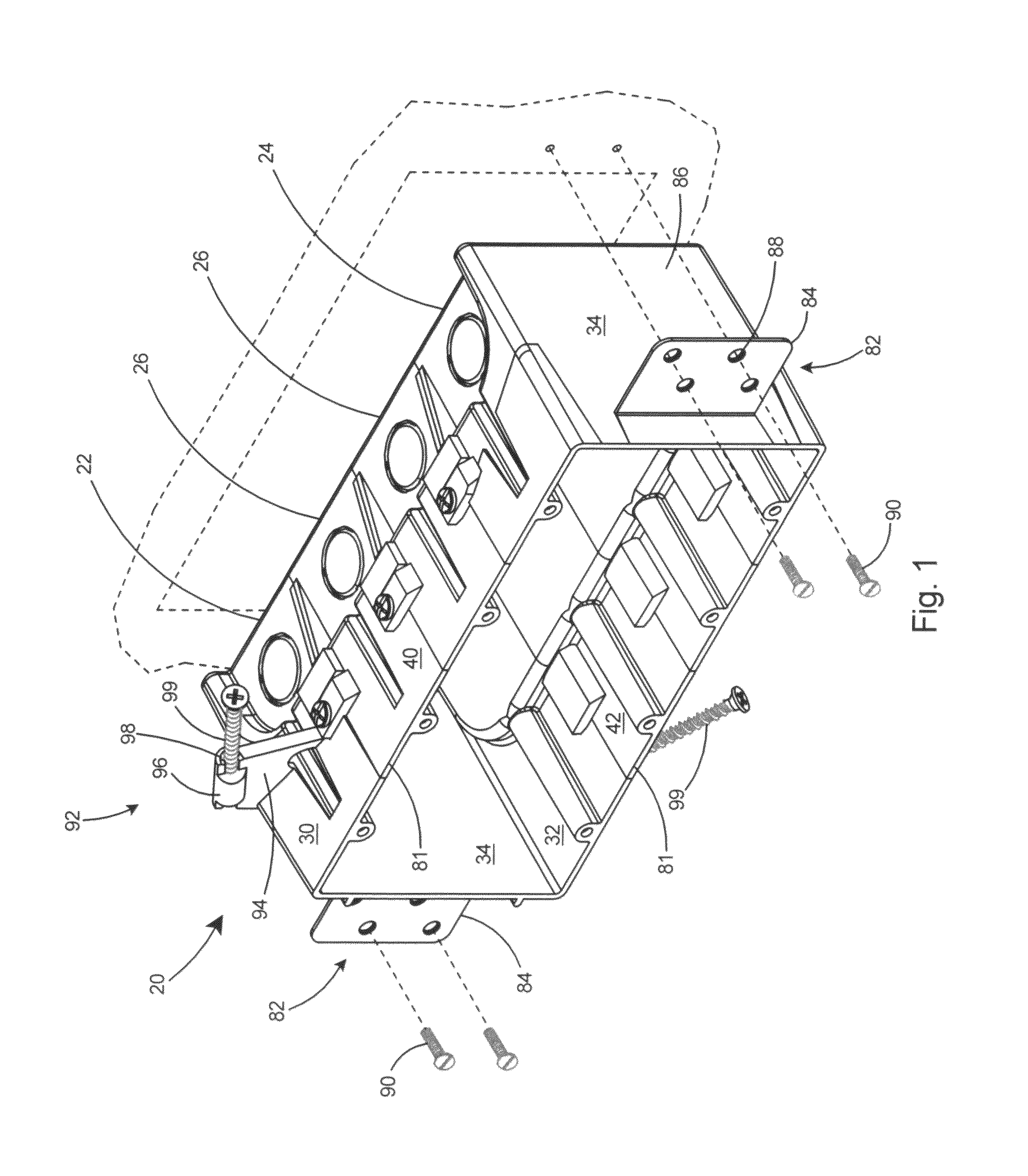
[0044]With reference to FIG. 9 there is shown a gangable modular electrical box assembly 100 according to the present invention. The gangable modular electrical box assembly 100 includes a third mounting arrangement 102 for mounting the assembled multi-gang box to a stud or similar support. The third mounting arrangement 102 includes an open channel 104 in a side wall 34 of first end body member 22, a screw plate 106 for insertion in the channel 104, and a locking arrangement 108 for locking the screw plate 106 into the channel 104. The locking arrangement 108 includes a boss 110 with a bore 112 therein on the screw plate 106 and an arm 114 extending from the side wall 34 adjacent the channel 104. The arm 114 includes an aperture 116 therein and a captive fastener 118 in the boss 110.

[0045]As shown in FIG. 10, after the screw plate 106 is inserted into the channel 104, a portion of the captive fastener 118 is driven into the aperture 116 in the arm 114 (see FIG. 9) thereby locking s...

third embodiment

[0046]Referring to FIG. 13 there is shown a gangable modular electrical box assembly 130 according to the present invention. The gangable modular electrical box assembly 130 includes a fourth mounting arrangement 132 including a peripheral flange 134 extending orthogonally from the front edges 81 of the top wall 30, bottom wall 32, and side walls 34 of the end bodies 22 and 24, oversize apertures 138 in the peripheral flange 134, mounting fasteners 140 extending through the oversize apertures 138 in the peripheral flange 134, and rotatable flags 142 connected to the mounting fasteners 140. With the gangable modular electrical box assembly 130 assembled into a multi-gang electrical box as shown in FIG. 14, mounting fasteners 140 are rotated at least 90 degrees counterclockwise to place the flags 142 flush against outer surface 66 of top walls 30 and bottom walls 32 and thereby minimize the outer profile of the box assembly 130. Box assembly 130 can then be inserted into a hole in the...

fourth embodiment

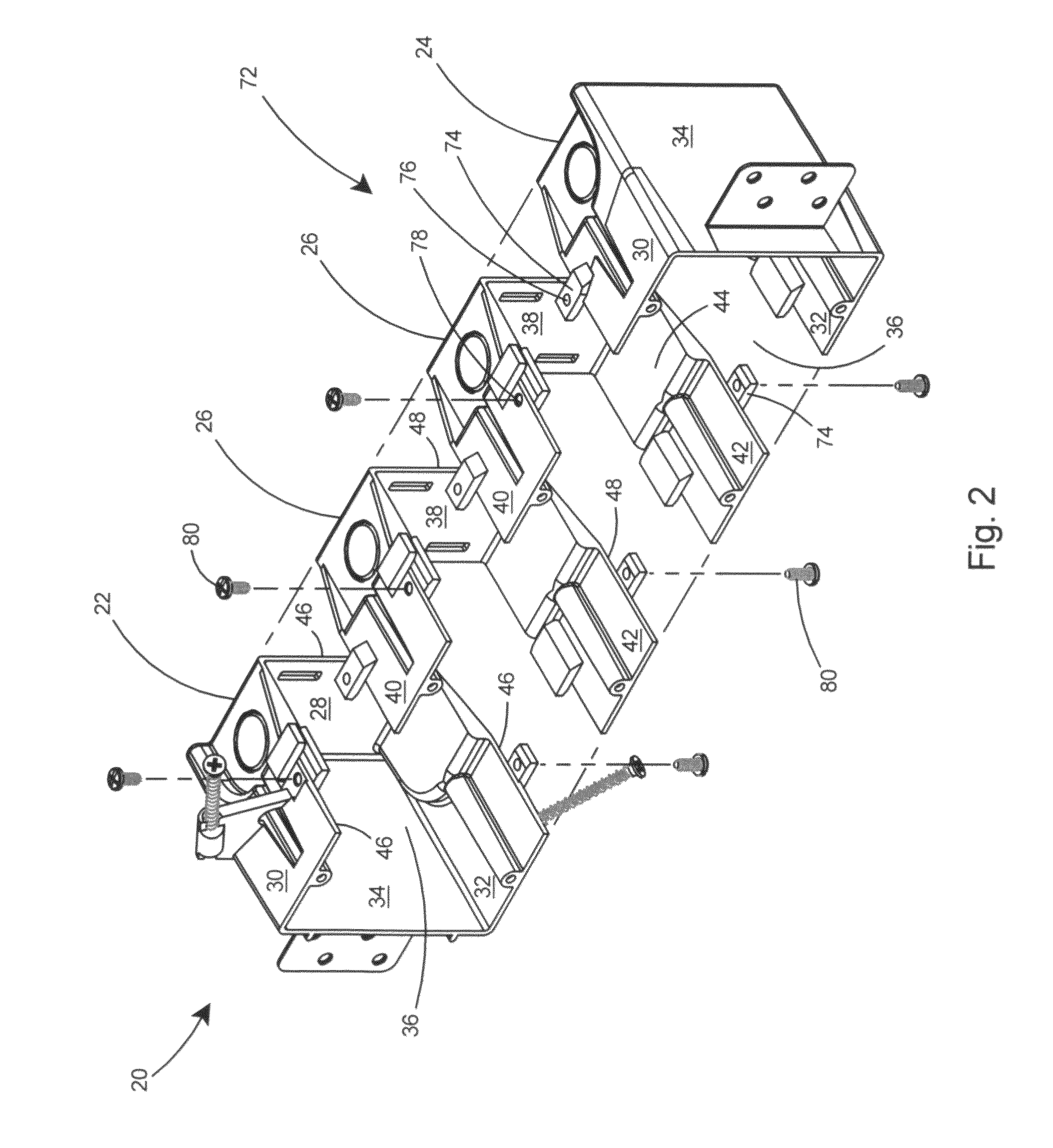
[0047]With reference to FIG. 18 there is shown a gangable modular electrical box 150 according to the present invention assembled in a configuration to provide a three-gang electrical box. As shown in FIG. 19, the gangable modular electrical box assembly 150 includes a snap fit fastening arrangement 152 on the assembly for snap-fitting the first end body 22, inner body 26, and second end body 24 (not shown) together. The snap fit fastening arrangement 152 includes a resilient locking tab 154 extending from the side edge 46 of the top wall 30 of the first end body 22 and a resilient locking tab 154 extending from the side edge 48 of the bottom wall 42 of the inner body 26. In addition, a resilient locking tab 154 is included on the back wall 28 of the first end body 22 and the back wall 38 of the inner body 26 and for snap-fitting and locking the back walls 28 and 38 of adjacent modules together. In addition, alignment tabs 156 are provided on the opposite sides of the walls from the...


PUM


Abstract

A gangable modular electrical box including separate modules that can be combined in various configurations to provide a desired amount of electrical enclosures on a wall. The modules include an end module and an optional inner module that are each molded in one piece of plastic. A rapid alignment and connection arrangement is included on the various modules to facilitate easy assembly of the modules at the job site without the use of sophisticated tools. The modules can be combined to form a two-gang, three-gang, or larger ganged box as desired. In the simplest configuration, two end modules can be combined to create a two-gang electrical box.

Description

FIELD OF THE INVENTION[0001]This invention relates to assemblies for the mounting of electrical devices and specifically to a gangable modular electrical box assembly that includes interlocking modules that can be joined together by an installer at the job site to form an electrical box having a desired number of electrical compartments.BACKGROUND OF THE INVENTION[0002]With the plethora of electrical devices found in the modern household, it is frequently necessary to install additional electrical receptacles to provide the required number of outlets. Although outlets can be provided by power strips, these devices are likely to be unsightly and difficult to child-proof as compared to outlets installed in the wall.[0003]Many types of electrical boxes are commercially available, including single receptacle boxes, two-gang boxes, three-gang boxes, and so on. However, it would be beneficial to an installer to have available at the job site the ability to assembly a multi-gang box of the...

Claims


Application Information

Patent Timeline
Patent Type & Authority Patents(United States)
IPC IPC(8): H01H9/02
CPCH02G3/12H02G3/086Y10S248/906
Inventor GRETZ, THOMAS J.
Owner ARLINGTON INDS
Why Eureka
Try Eureka