Electrical connector

Inactive Publication Date: 2005-04-05
SPEED TECH
View PDF8 Cites 8 Cited by
  • Summary
  • Abstract
  • Description
  • Claims
  • Application Information

AI Technical Summary

Benefits of technology

It is therefore a primary object of the invention to provide an improved electrical connector, comprising an insul

Problems solved by technology

However, the request of alignment of soldering portion is raised and it is not easy for manufacturing, especially for the component with curved terminals, because the terminal is softy.
Thus, the manufacturing efficiency would be declined and the assembly cost would be increased, if the manufacturing

Method used


Image

  • Electrical connector
  • Electrical connector
  • Electrical connector

Examples


Embodiment Construction

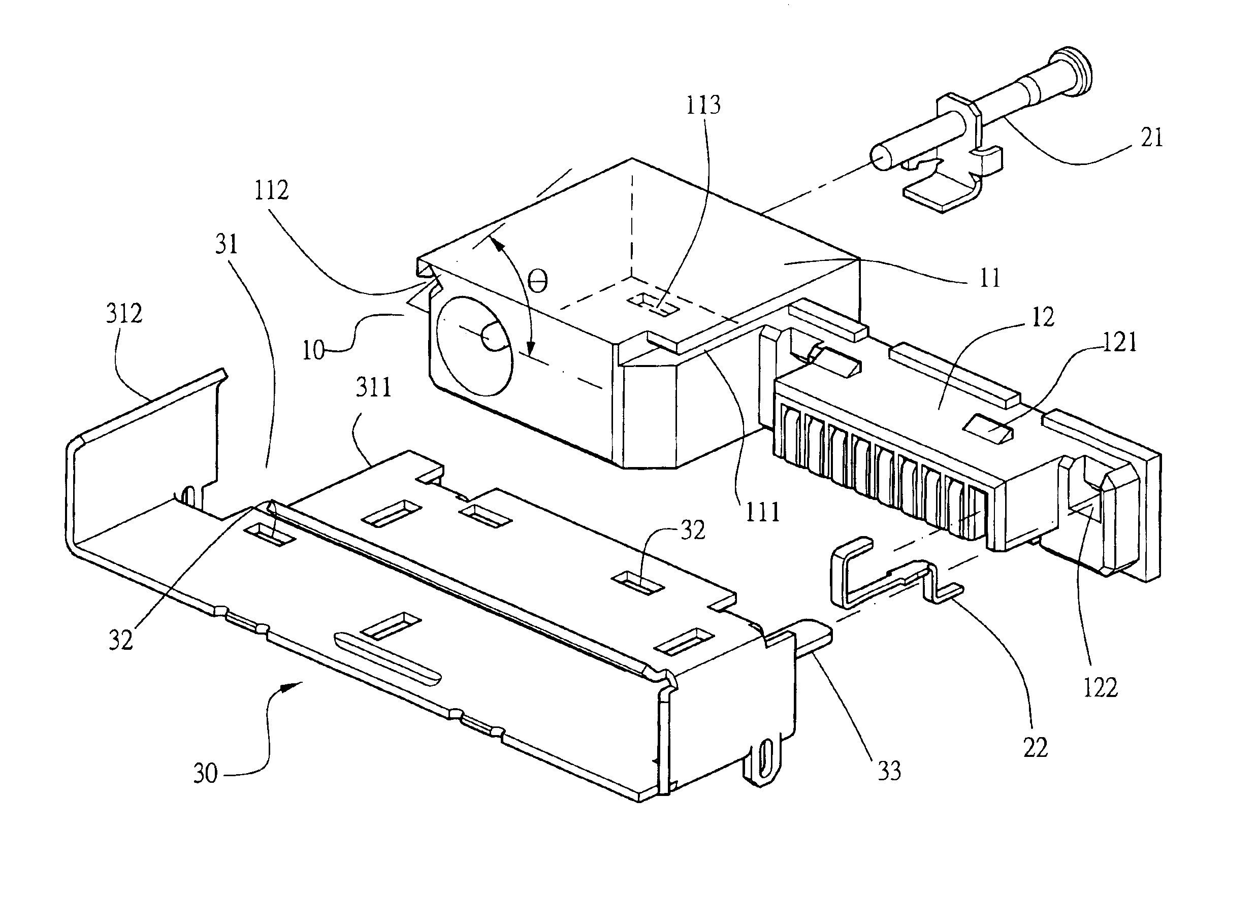
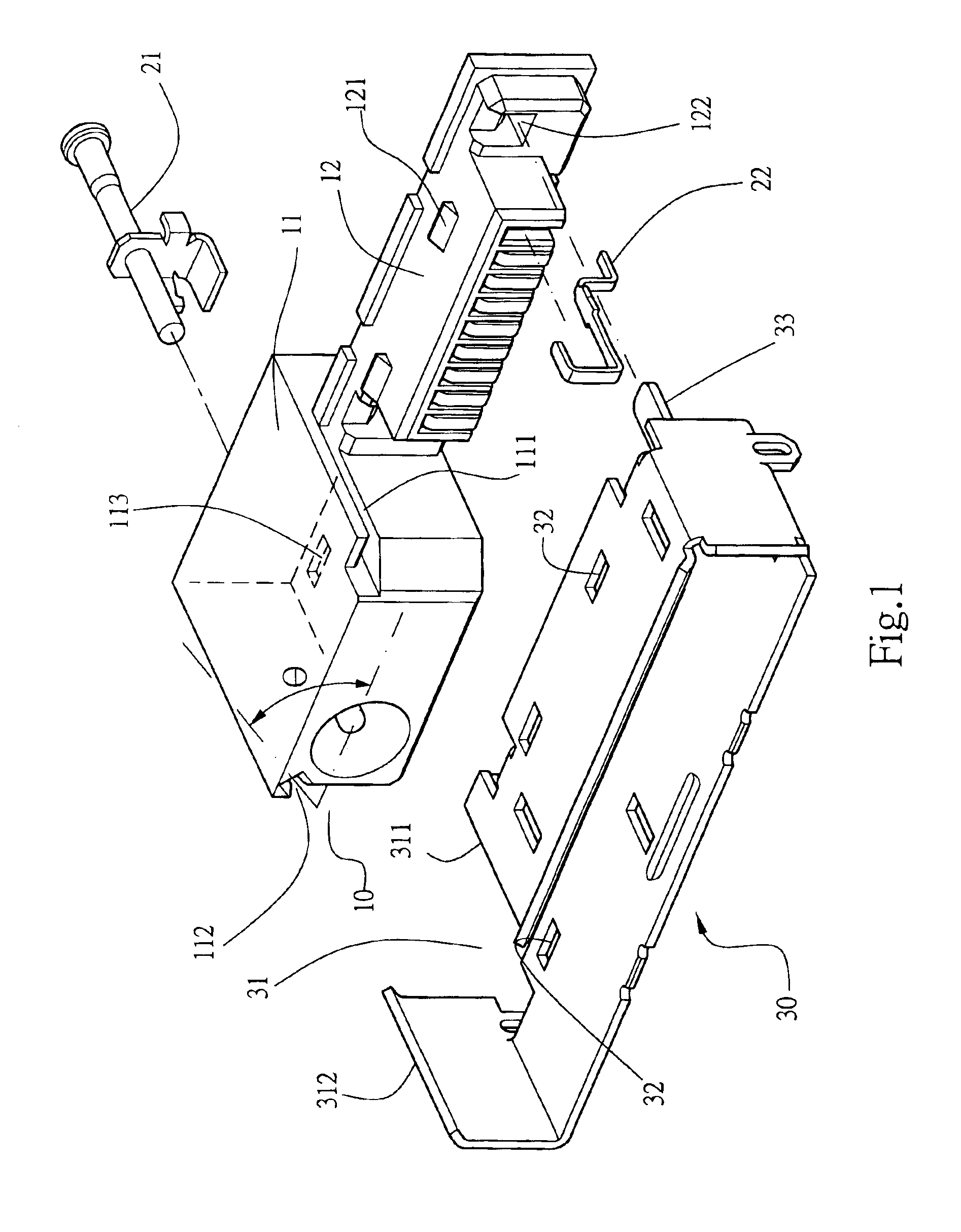
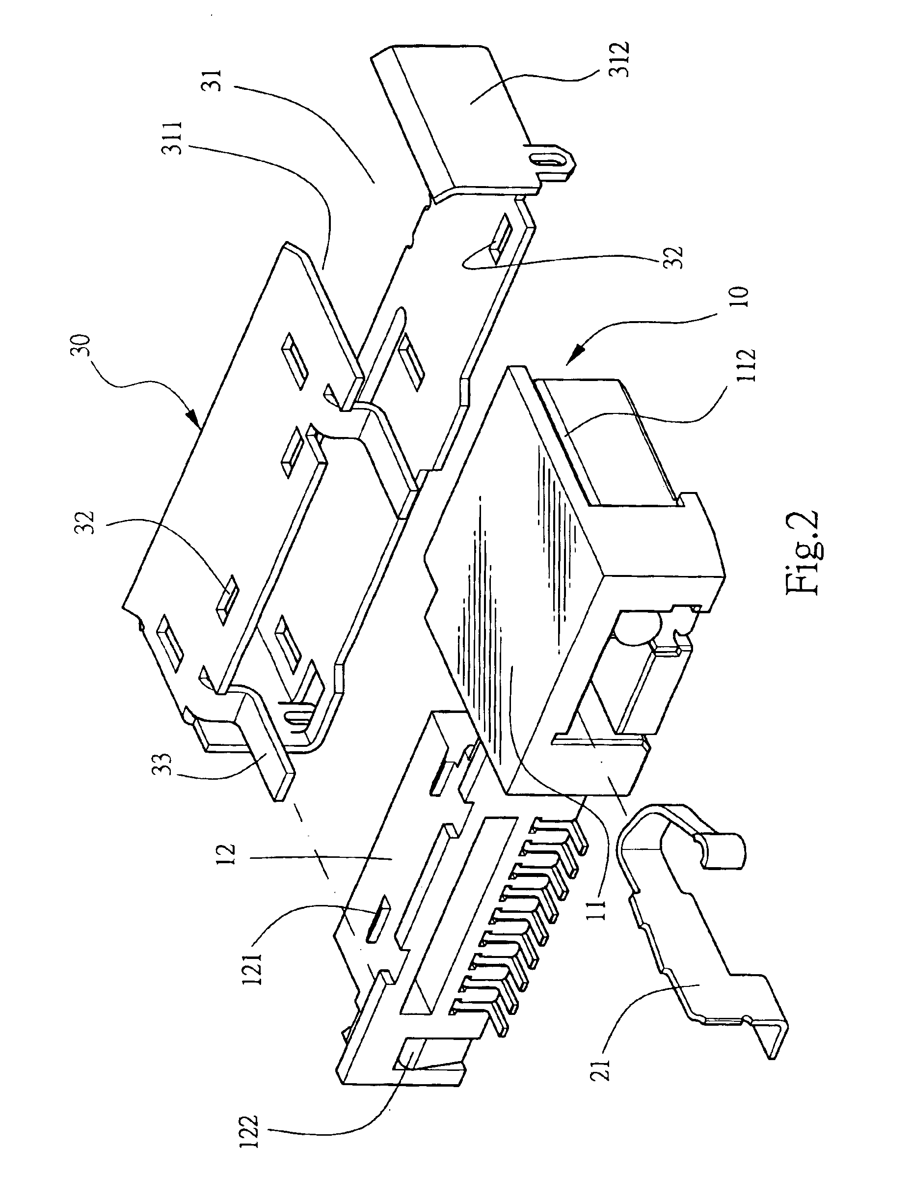
Referring to FIG. 1 and FIG. 3, the electrical connector 1 of the present invention comprises an insulating housing 10 with two communication ports, such as a power port 11 and a signal port 12, having lower profile than the power port 11 in this embodiment of this invention, a SMT type power terminal 21, and signal terminals 22 are inside the insulating housing 10, wrapped by a metal shield 30 and fixed on a PCB 40. The insulating housing 10 further having a sliding slot 111 located on upper side of the insulating housing 10 near the signal port 12, and a fastening slot 112 slant upward on the insulating housing 10 near the upper corner of the power port 1.

The metal shield 30, made by a sheet metal, is in rectangular. The metal shield 30 having an opening 31 between two ends, a protruding end 311 and a fastening end 312. The protruding end 311 of the metal shield is corresponding to the sliding slot 111 of the insulating housing 10 near the signal port 12, and the fastening end 312...


PUM


Abstract

An electrical connector includes an insulating housing with two communication ports and wrapped by a metal shield. The invention features on that the insulating housing having a sliding slot located on upper surface of the insulating housing near one of said communication port, and a fastening slot slanted bias on the insulating housing near the other communication port. The metal shield having an opening between two ends, a protruding end on one end, corresponding to the sliding slot of the insulating housing, and a fastening end, opposite to the protruding end, slants bias and corresponds to the fastening slot of the insulating housing near. The metal shield can be assembled onto the outer surface of the insulating housing rapidly and easily.

Description

BACKGROUND OF THE INVENTIONI. Field of the InventionThis invention relates generally to an improved electrical connector and, more specifically, to a connector with two communication ports, such as a power and a signal port. for mobile devices, such as phones and PDAs (Personal Data Assistance).II. Description of the Prior ArtIt is known that the electrical connectors, with a power and a signal port, arranged and soldered onto the PCB (printed circuit board) inside of mobile devices for communication with other electrical devices, are generally soldered by SMT, Surface Mount Technology, manufacturing process, and the alignment of the soldering portion of the terminals in said components determinates the electrical connection between said components and the PCB is failed or not. To avoid short between terminals in fine pitch electrical components soldered on the PCB, the thickness of the solder is declined and the alignment of the soldering portion of terminals must be more precise. ...

Claims


Application Information

Patent Timeline
IPC IPC(8): H01R12/16H01R12/00
CPCH01R23/6873H01R12/712H01R13/658H01R2201/16
Inventor CHU, CHANG-SINGHSU, WEN LUNG
Owner SPEED TECH
Why Eureka
Try Eureka