Sub-flooring assembly and method

a subfloor and assembly technology, applied in the direction of walls, fastening means, mechanical equipment, etc., can solve the problems of difficult stacking and shipping, difficult assembly of metal sub-frame floors, and relatively slow assembly of stringer sub-floors, etc., to achieve easy and rapid assembly, easy alignment and releasability, and excellent load bearing characteristics

Active Publication Date: 2008-12-09
SUR LOC HLDG LLC
View PDF22 Cites 11 Cited by
  • Summary
  • Abstract
  • Description
  • Claims
  • Application Information

AI Technical Summary

Benefits of technology

[0005]The present invention is directed to a temporary sub-flooring assembly and more particularly to a load bearing temporary sub-flooring assembly which has interlocking sections. The disclosed sub-flooring is sturdy and has excellent load bearing characteristics, and can support the weight of vehicles and other heavy objects. The sub-flooring is easily and rapidly assembled into any desired size and shape, and may be easily aligned and releasably locked together. The system is cost effective, and easily stackable for ease of storage and transport. The disclosed flooring may be easily disassembled, and the sections reused.

Problems solved by technology

Assembly of stringer sub-floors is relatively slow and labor intensive.
Metal sub-frame floors are also relatively difficult and labor intensive to assembly.
In addition, the sections typically include protrusions, or ‘leg sleeves’, which are difficult to stack and ship.
As such, conventional web-lock flooring provides poor load capacity and is not overly rugged.
Many conventional flooring designs are not weather resistant, give they often include wood components or sections.
Such flooring designs are therefore subject to rotting, which could result in weak spots or render the flooring unusable.
Thus, many conventional flooring designs cannot be reused, or may only be reused a relatively limited number of times, particularly if they are used for outdoor applications.

Method used


Image

  • Sub-flooring assembly and method
  • Sub-flooring assembly and method
  • Sub-flooring assembly and method

Examples


Embodiment Construction

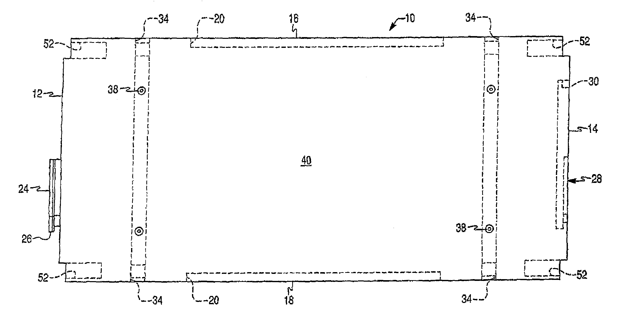
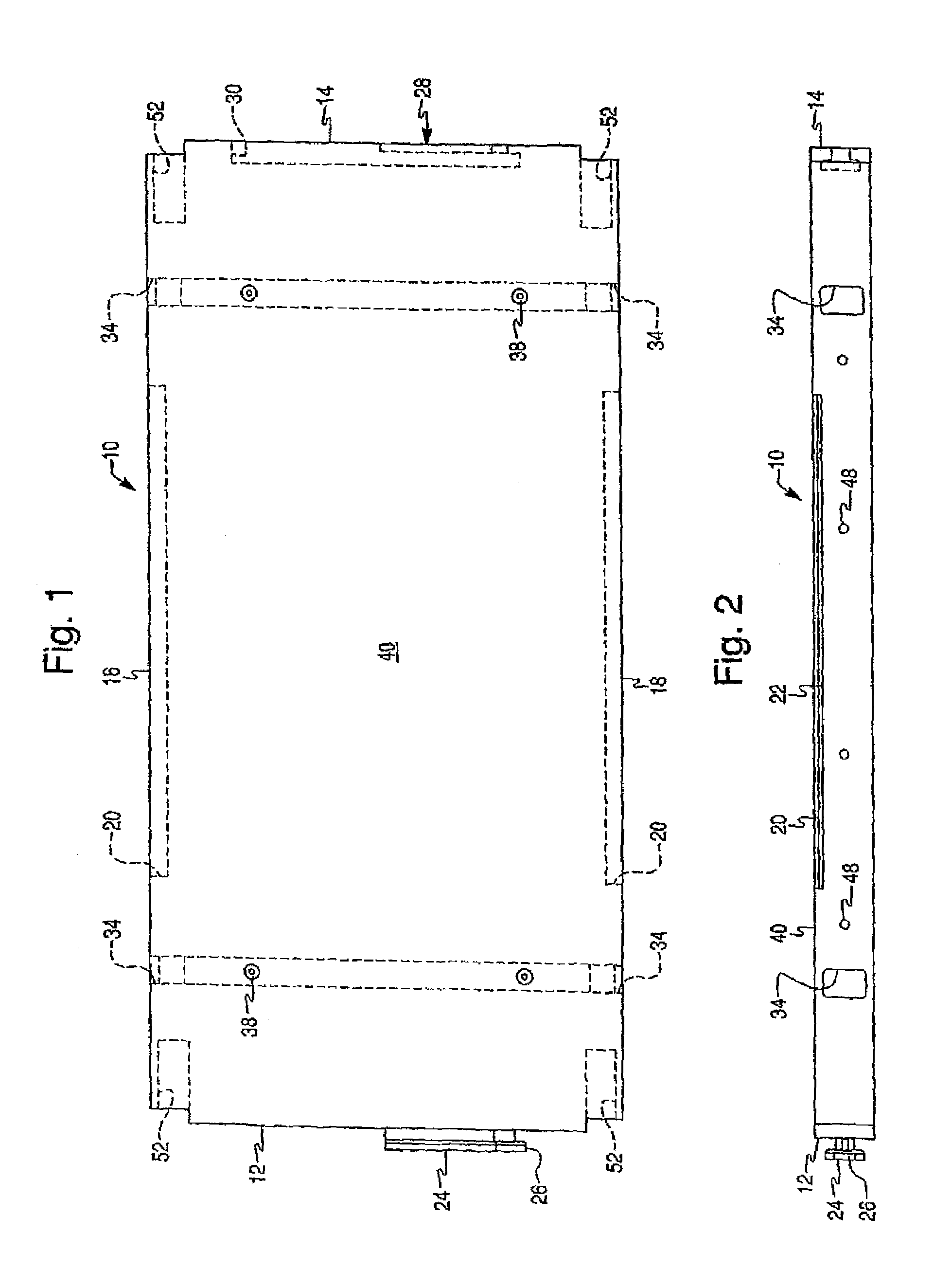
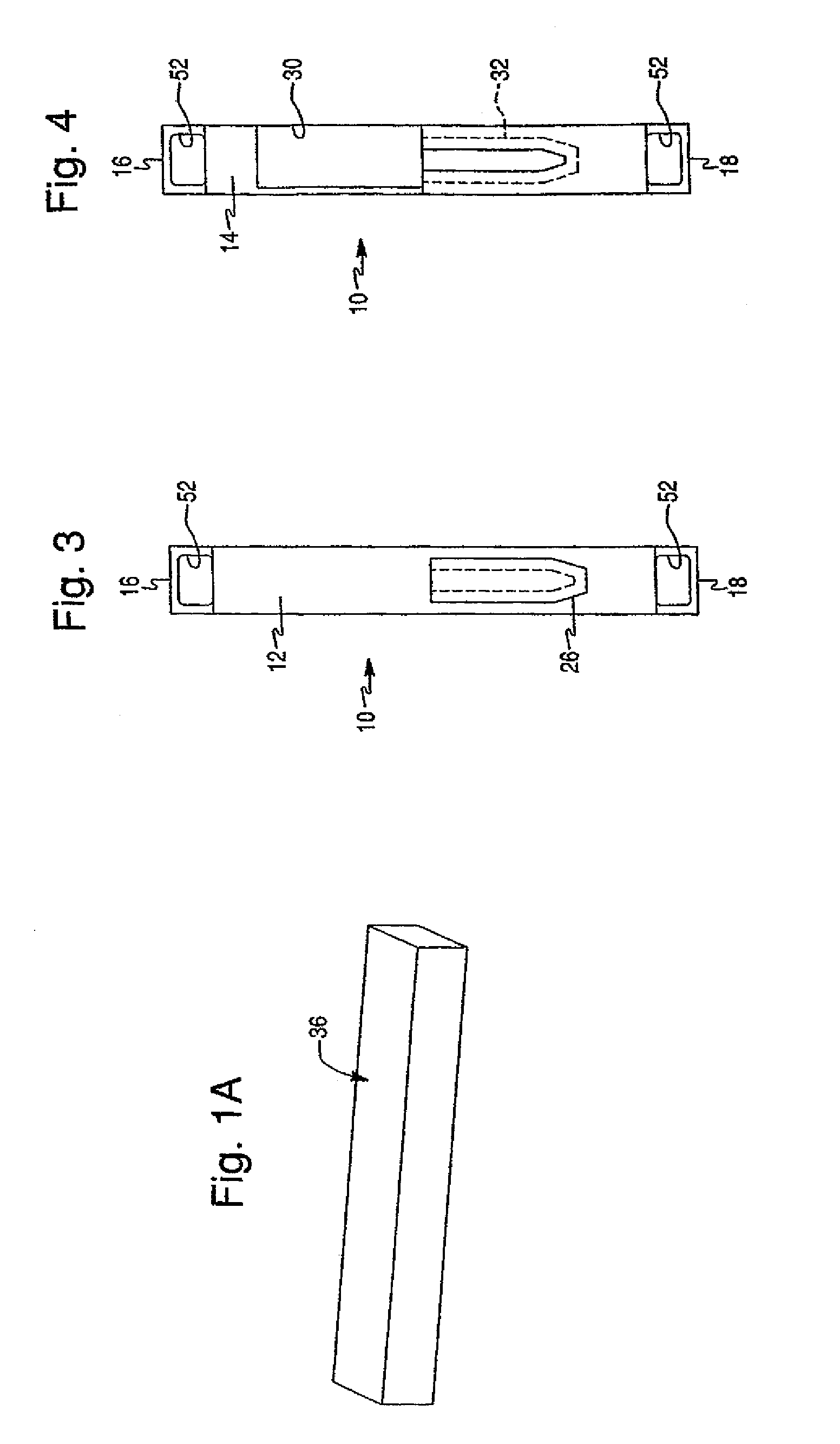
[0040]Referring to FIGS. 1-7, a sub-flooring assembly according to a first embodiment includes a plurality of sections 10 which are joined together end-to-end and side-to-side to form an assembly of any desired dimensions. The assembly may be easily disassembled to the individual sections when no longer needed. Preferably each section is rectangular having a first end 12, an opposite second end 14, a first side 16 and an opposite second side 18. It is preferred that the length of each end 12, 14 is about 2 feet and the length of each side 16, 18 is about 4 feet. However, the specific dimension of each section 10 is not so limited. For custom assemblies, sections of different dimensions may be used. Preferably, each section 10 has a height of 3 inches, but the invention is not so limited.

[0041]A receiver channel 20 is formed longitudinally on each side of each section 10. A rigid insert 22 is disposed in each receiver slot 20 to provide support to the section, to reduce flexibility o...


PUM

PropertyMeasurementUnit
lengthaaaaaaaaaa
lengthaaaaaaaaaa
heightaaaaaaaaaa

Abstract

The present invention is directed to a sub-flooring assembly. The disclosed assembly includes at least two rectangular sections. Each of the sections have first and second ends and first and second sides. A male component extends outwardly from the first end of each of the sections. The male component has a flange proximate a free end thereof. An opening is disposed on the second end of each of the sections. The opening extends into the section to form a cavity. A pocket is formed in the cavity. The flange of one of the sections is removably received in the pocket of another of the sections for detachably securing the first end of one of the sections to the second end of another of the sections.

Description

FIELD OF THE INVENTION[0001]The present invention is directed to a sub-flooring assembly. The disclosed assembly includes at least two rectangular sections. Each of the sections have first and second ends and first and second sides. A male component extends outwardly from the first end of each of the sections. The male component has a flange proximate a free end thereof. An opening is disposed on the second end of each of the sections. The opening extends into the section to form a cavity. A pocket is formed in the cavity. The flange of one of the sections is removably received in the pocket of another of the sections for detachably securing the first end of one of the sections to the second end of another of the sections.BACKGROUND OF THE INVENTION[0002]Various conventional temporary sub-flooring designs are known. Stringer sub-floors include wooden strips 2′×8′ or 2′×6′. The strips are spaced two feet apart, and covered with sheets of plywood which are secured to the strips with s...

Claims


Application Information

Patent Timeline
Patent Type & Authority Patents(United States)
IPC IPC(8): E04F15/00
CPCE04F15/02E04F15/10E04F2201/0123E04F2201/035E04F2201/05E04F2201/0523F16B5/0036
Inventor CERASI, MARK A.KUBIC, DAVID
Owner SUR LOC HLDG LLC
Why Eureka
Try Eureka