Child Safety Gate

a child safety and gate technology, applied in the field of child safety gates, can solve the problems of not being useful around narrow openings or openings with a minimum of space, not being able to accommodate skirting boards, floor mouldings, etc., and not being able to meet the needs of children,

Inactive Publication Date: 2014-10-30
BABY
View PDF13 Cites 8 Cited by
  • Summary
  • Abstract
  • Description
  • Claims
  • Application Information

AI Technical Summary

Benefits of technology

[0018]The gripping part is configured as a pin optionally with a head or an elevation, and the receiving part is configured as a second groove or a depression in which the pin may be arranged. The gripping part is configured as a pin, and the receiving part is configured as a pin hole in which the pin may be arranged, and the pin and the pin hole are disposed opposite each other on the inner side of the panel parts. Hereby, it is possible to join the individual panel parts in an easy and simple manner.
[0019]In a special embodiment, the mounting fitting comprises a wall part intended to be mounted in the opening and a panel part connected with the first end panel, said panel part being capable of rotating about the wall part. The wall part comprises a first central member connected with the two first end members, said first central member comprising a third groove, e.g. a cylinder section, in which the panel part may be disposed. The panel part comprises a second central member connected with two second end members, said second central member and said two second end members being cylindrical. Hereby, it is possible to provide a

Problems solved by technology

The known systems, however, have the drawback that they occupy a good deal of space around the opening in order to be able to open properly.
Therefore, they are not useful around narrow openings or openings with a minimum of space.
Moreover, the known child safety gates do not allow for skirting boards, floor mouldings, etc., which may be mounted in the openings.
This structure, however, may have the drawback that if the user releases the door after it has been opened, the door will perform an uncontrolled rolling-together at the opposite end because of the spring force.
This may inv

Method used


Image

  • Child Safety Gate
  • Child Safety Gate
  • Child Safety Gate

Examples


first embodiment

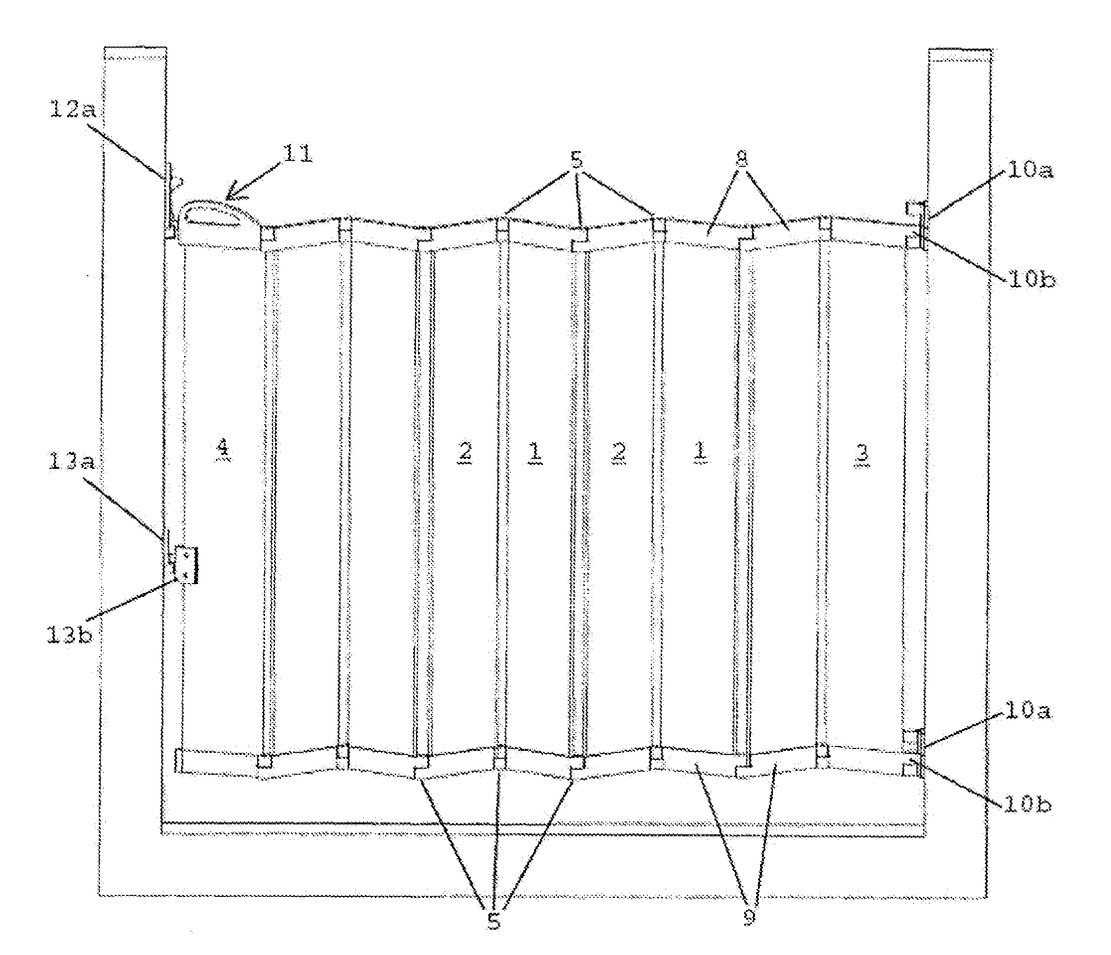
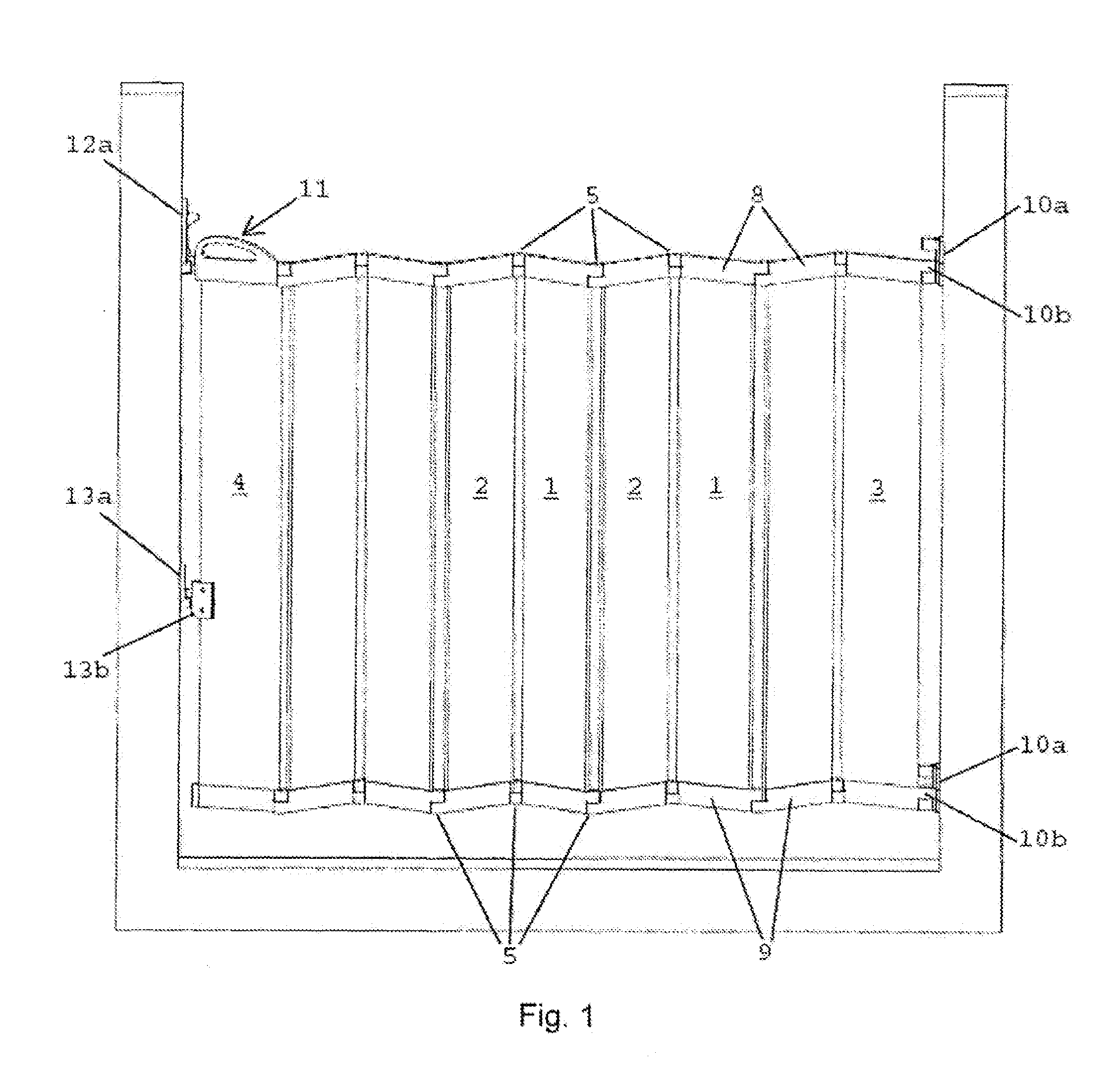
[0039]FIG. 1 shows the invention mounted on a door frame in a closed position. FIG. 2 shows the invention shown in FIG. 1 in an open position. The invention comprises a child safety gate comprising one or more panels 1, 2, 3, 4, which may be mutual with each other, and which may be mounted in an opening, such as a door opening, a staircase opening, a corridor or passage, an entrance or the like. At least one hinge 5 may be disposed between each of the panels 1, 2, 3, 4, which hinge may be connected with the panel on both sides of the hinge, whereby the panels 1, 2, 3, 4 may be moved relative to each other. The child safety gate comprises two end panels 3, 4 disposed at their respective sides of the gate and a plurality of intermediate panels 1, 2, as shown in FIG. 1. The end panel 3 may be connected with at least one fitting 10, which may be secured to the opening, such as a wall or a frame. The end panel 4 may be connected with at least one closure device 12, 13 and an optional han...

second embodiment

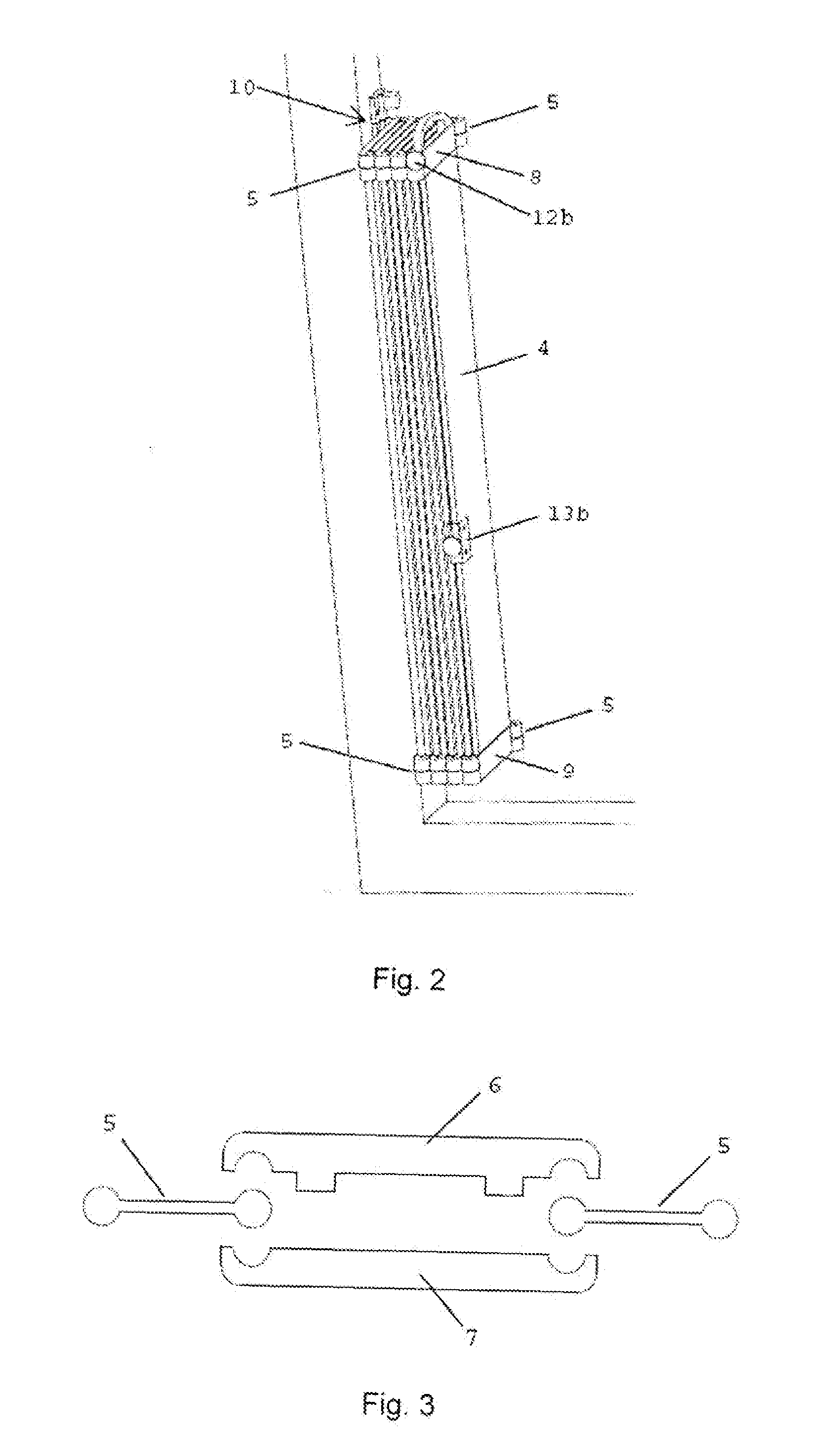
[0040]The panel 1, 2, 3, 4 may have a solid or hollow structure and have a quadangular, elliptic, circular or any other polygonal or round cross-section. In a second embodiment, the panel structure may comprise two or more panel parts 6, 7, which may be secured to each other by means of friction or fasteners, such as screws, bolts or glue, as shown in FIG. 3. The panel parts 6, 7 may comprise one or more male parts and / or one or more female parts disposed opposite each other, e.g. on the inner side of their respective panel parts. The male part and the female part may be constructed as a pin joint comprising a pin and a pin hole, respectively. The pin joint may comprise a head or an elevation and a corresponding depression or groove, so that the male part and the female part are snapped together. The width and / or the height of the individual panels 1, 2, 3, 4 and the panel parts 6, 7 may be varied, thereby making it possible to adapt the number of panels in the child safety gate to ...

third embodiment

[0051]FIG. 7 shows a cross section of a third embodiment, where the hinge 5 may be embedded in the panels 1, 2, 3, 4. The hinge 5 may be constructed as a rotating hinge 16 comprising a first hinge part 16a and a second hinge part 16b capable of rotating about the first part 16a. The hinge parts 16a, 16b may be connected with their respective panels 1, 2, 3, 4. FIG. 7 shows the hinge parts 16a, 16b connected with their respective ends of an intermediate panel 1, 2. The second hinge part 16b may be constructed as a hollow or solid ball comprising an outer surface 17 and optionally an inner surface 18. Alternatively, the second hinge part 16b may be constructed as a hollow or solid cylinder. The first hinge part 16a may be constructed as a ball or cylinder section 19, which may be conformed to the second hinge part 16b. The hinge parts 16a, 16b may be interconnected so that the first hinge part 16a is capable of rotating about a central axis in the second hinge part 16b along the outer...


PUM


Abstract

The invention relates to a child safety gate which occupies as little space as possible when the gate is open. The child safety gate comprises two or more panels (1, 2, 3, 4) interconnected by at least one hinge (5). The panels are mounted in the opening via at least one fitting (10) connected with an end panel (3) at one side. At least one closure device (12, 13) is connected with an end panel (4) at the other side. The hinges (5) may be connected with the panels (1, 2, 3, 4), so that the panels may be folded inwardly over each other when the gate is opened. A panel top (8) and/or a panel base (9) may be connected with the panels. The panels (1, 2, 3, 4) may comprise two panel parts which may be telescoped. An extension panel may be disposed between the panel parts.

Description

TECHNICAL FIELD[0001]The present invention relates to a child safety gate intended to be mounted in an opening, such as door openings or staircase openings, and comprising two or more panels which may be connected with each other, a mounting fitting intended to be mounted at one side of the opening, and a closure device intended to be mounted at the opposite side of the opening, wherein at least one of the panels is capable of rotating about a first axis of rotation in the mounting fitting.THE PRIOR ART[0002]Today, child safety gates are preferably constructed as rigid gate doors comprising an upper member and a lower member between which a plurality of vertical bars are mounted. These gate doors are mounted either directly on the wall or the frame in an opening or between one or two fixed gates. Frequently, these child safety gates have a post which is mounted directly on the wall, or a transverse member at the bottom.[0003]U.S. Pat. No. 5,367,829 A describes a child safety gate mo...

Claims


Application Information

Patent Timeline
IPC IPC(8): E06B9/06E06B11/02
CPCE06B9/06E06B2009/002E06B11/022E06B9/0638E06B9/0669E05B65/0014E06B9/0607
Inventor PEDERSEN, HENRIK LMOLLER-NIELSEN, TINA
Owner BABY
Why Eureka
Try Eureka