Multi-component hearing aid system and a method for its operation

a hearing aid system and multi-component technology, applied in the field of multi-component hearing aid systems, can solve the problems of limited maximum transmit power of such hearing aid system components that are to be worn close to the ear, limited miniaturization, and interference power of said components, so as to reduce interference power

Active Publication Date: 2012-07-03
SIVANTOS PTE LTD +1
View PDF28 Cites 2 Cited by
  • Summary
  • Abstract
  • Description
  • Claims
  • Application Information

AI Technical Summary

Benefits of technology

[0018]With the deactivation of the sources of interference or, as the case may be, a reduction in the interference power or a manipulation of the interference spectrum, the reception situation in a receiving component of the hearing aid system, i.e. an auxiliary device for example, can be considerably improved temporarily at precisely defined times without noticeably compromising the performance of the individual components in normal operation if the change in the operating mode of the sources of interference only takes place in short time windows in which deviations from the normal operation of the hearing aid system that occur are not perceptible.
[0019]In certain cases changes in the operating mode of sources of interference are also conceivable which involve deviations from the normal operation of the hearing aid system that lie above the perceptibility threshold. Since the data transmission from a hearing aid system component that is to be worn close to the ear to an auxiliary device is for example an operating situation which occurs very infrequently in the normal application of a hearing aid system, for example during a programming session when the hearing aid data is being read out or in the case of an interrogation of the status of the hearing aid components by a remote control, the possibly perceptible performance restriction associated therewith is tolerable. Thus, the momentary deactivation of the hearing aid earpiece or a display unit on the auxiliary device will scarcely have disruptive effects.
[0021]The change in the operating mode of the identified sources of interference, where appropriate their deactivation, advantageously takes place during the transmission of data in all components of the hearing aid system which, during the existence of the wireless communication connection, are located in the vicinity of receivers involved. The deactivation or, as the case may be, change in the operating mode of the sources of interference both in the receiving component and in the sending component has the advantage that the influence of sources of interference in the sending component which can also cause reception problems or interference in the receiver of the receiving component in the local area when there is a relatively small distance between transmitter and receiver is also reduced or excluded. In this way an adverse effect on the transmission of data in the case of very short distances between the individual components of the hearing aid system due to design factors is precluded.

Problems solved by technology

Adverse effects of said kind can result, for example, from an inappropriate weight of the hearing aid or from, say, restrictions on movement associated with the wearing of hearing aids.
However, there are limits to said miniaturization due to the increasing complexity and functionality of modern hearing aids, which is why multi-component systems have become established in which individual functions of the hearing aid have been exported into an auxiliary device or other components that are to be positioned independently of the ear.
With the inductive wireless transmission of data from a hearing aid system component that is to be worn close to the ear to a device equipped with a suitable receiving apparatus, for example an auxiliary device in the form of a relay station, a programming device or a remote control, there is the problem that due to the relatively low capacity, voltage and peak-current-carrying capacity of batteries that are typically used, the maximum transmit power of such hearing aid system components that are to be worn close to the ear is also very limited.
This results in a correspondingly short transmission range.
Due to the low level of the useful signal at the receiving apparatus, even very low-power sources of interference can massively influence the transmission quality or impede or prevent the identification of the data that is to be transmitted.
Due to their very design, however, essential components of a hearing aid system, including auxiliary devices designed to receive data, generate electromagnetic emissions which act as sources of interference during the data transmission and during the data transmission are situated between the individual components in immediate proximity to the transmission link, in particular to the active receiver in each case, i.e. in inductive systems close to the active receiving coil in each case.
Sources of interference of this kind are, for example, the inductances of clocked voltage regulators or the supply and output lines of practically all clocked electronic circuits.
In the actual hearing aid, i.e. in components that are to be worn close to the ear, the hearing aid earpiece itself can contribute an additional source of interference.
However, effective shielding of magnetic interference fields requires the use of components with relatively large space requirements, for example in μ-metal boxes.
In particular in the case of hearing aid components that are to be worn in or on the ear, the necessary space for this is usually not available and the weight disadvantage associated therewith not acceptable.
A sufficiently great distance between the receiving coil and modules acting as sources of interference can likewise not be provided in particular in the case of hearing aid components that are to be worn in or on the ear.
This, however, leads to significant restrictions in terms of design freedom and degree of miniaturization of devices configured in such a manner.

Method used


Image

  • Multi-component hearing aid system and a method for its operation
  • Multi-component hearing aid system and a method for its operation
  • Multi-component hearing aid system and a method for its operation

Examples


Embodiment Construction

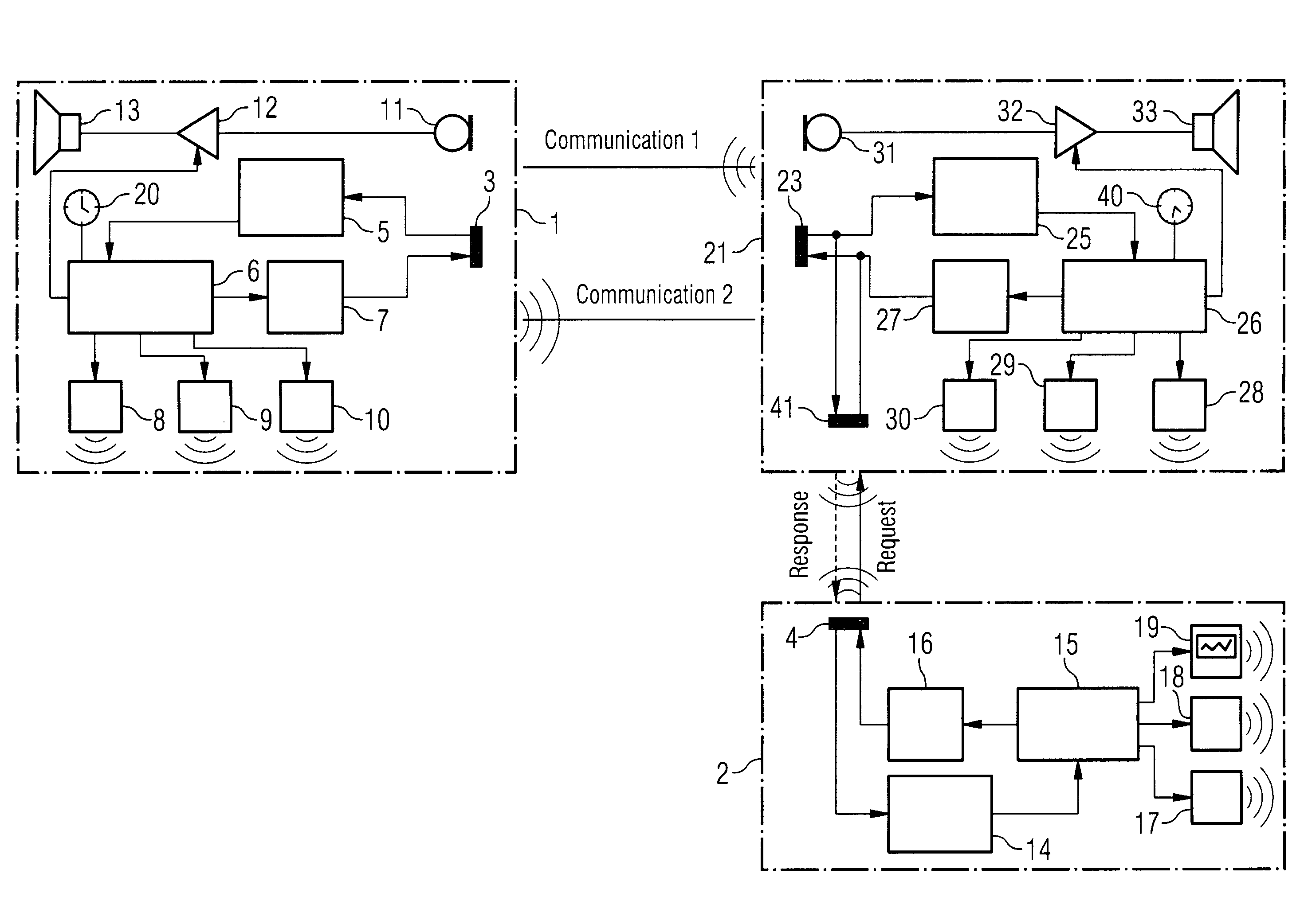
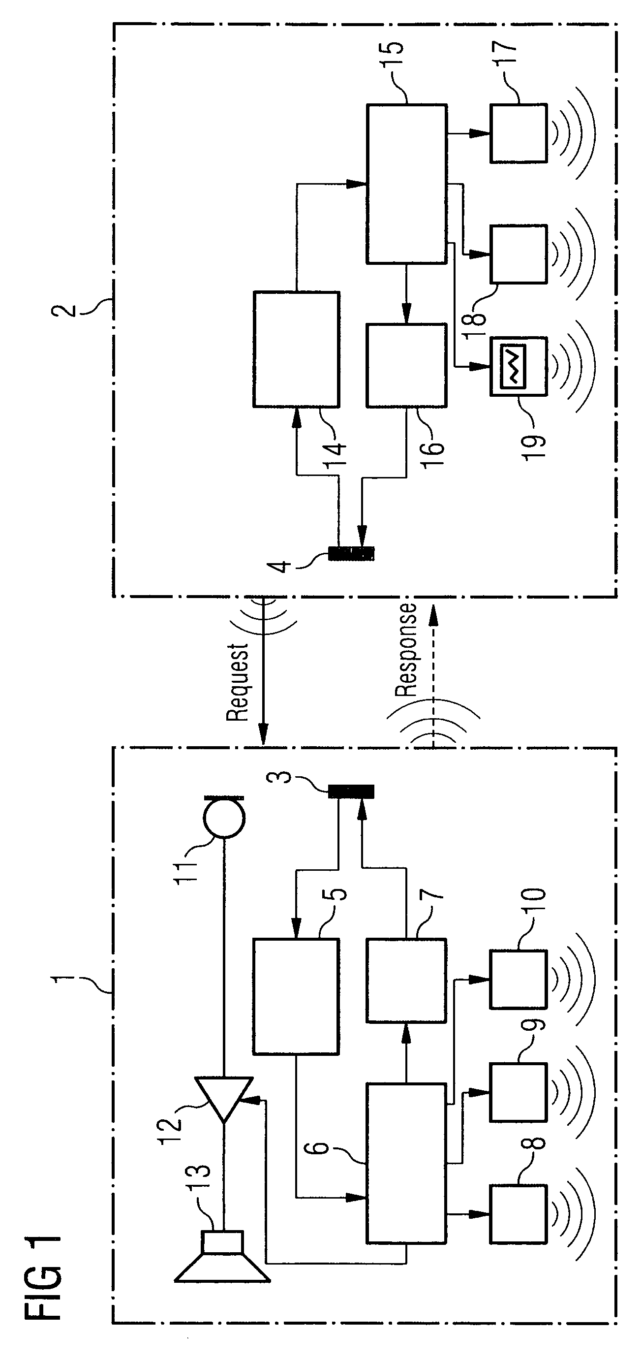
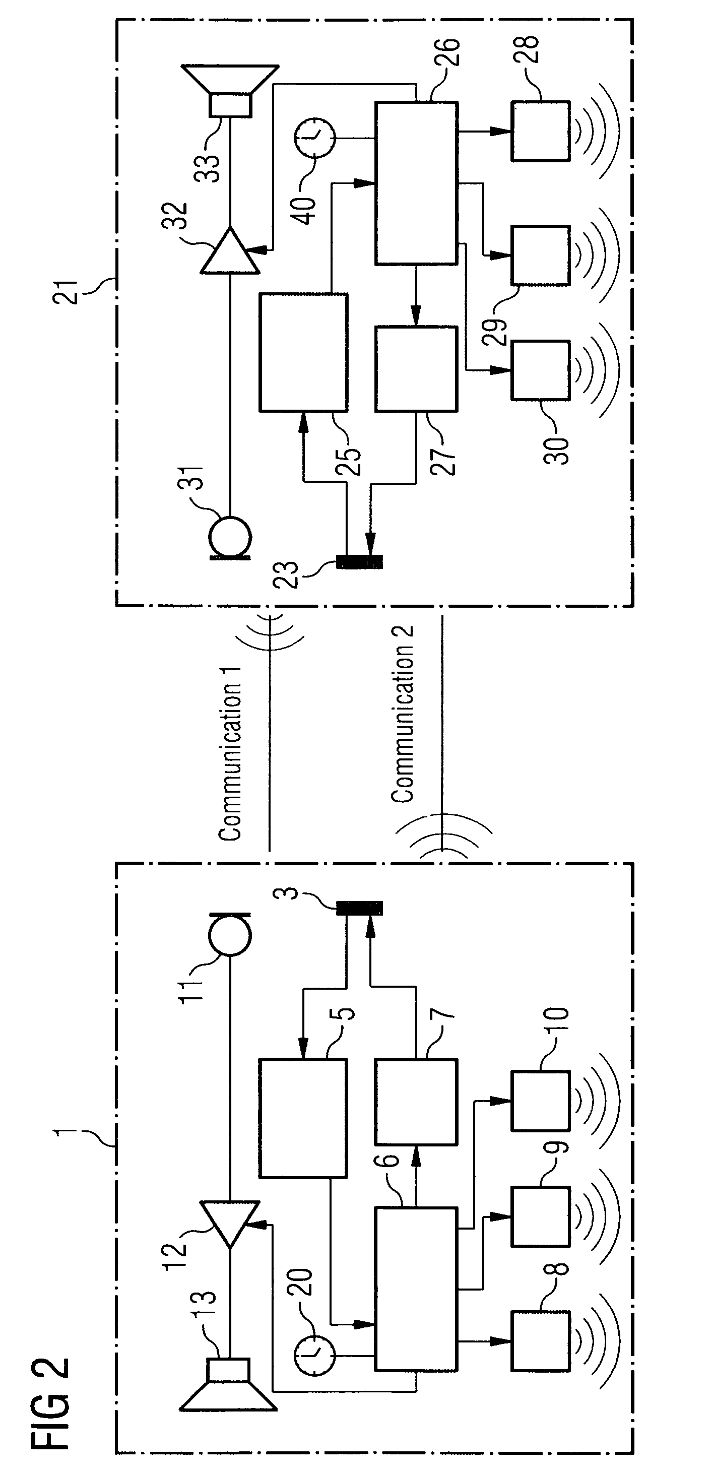
[0026]FIG. 1 shows a schematic circuit diagram of a hearing aid system according to the invention, consisting of two components. The two components of the hearing aid system are a hearing aid component 1 designed to be worn on the ear of a patient for the purpose of amplifying sound pressure and an auxiliary device 2 by means of which individual acoustic parameters of the hearing aid component to be worn on the ear can be set, as can be carried out by the patient him- / herself with the aid of a remote control for example. In an alternative that is not shown, the auxiliary device can also be a programming device of a hearing aid acoustician.

[0027]In order to carry out the settings, a communication is required for the purpose of data transmission between the hearing aid component 1 and the auxiliary device 2. During the data transmission the auxiliary device 2 is brought close to the ear-worn hearing aid component 1 so that it is situated within range of the data transmission means dis...


PUM


Abstract

The invention relates to a multi-component hearing aid system, comprising at least one first component that is designed to be disposed on or in the ear of a patient for the purpose of generating and / or amplifying an auditory stimulus and at least one further component which can engage at least partially and / or temporarily in a wireless communication connection via which a data transmission can take place with the first component that is to be worn on or in the ear, wherein circuitry means are included which can place at least one source of interference contained in the hearing aid system at least during the transmission of data into an operating mode in which interference signals are coupled by said at least one source of interference into a receiver involved in the data transmission in a manner that is at least attenuated compared to the normal operating mode.

Description

CROSS REFERENCE TO RELATED APPLICATIONS[0001]The present application claims the benefit of a provisional patent application filed on Jul. 2, 2007, and assigned application No. 60 / 958,089, which is incorporated by reference herein in its entirety.FIELD OF THE INVENTION[0002]The invention relates to a multi-component hearing aid system as well as to a method for its operation, in particular for data transmission between components of the hearing aid system.BACKGROUND OF THE INVENTION[0003]Hearing aids serve primarily for providing hearing-impaired patients with as natural a hearing sensation as possible and in this regard compensate for usually medically induced malfunctions of the acoustic organs. At the same time, like most medical aids, they have to fulfill this functionality without provoking other adverse effects for their wearer. Adverse effects of said kind can result, for example, from an inappropriate weight of the hearing aid or from, say, restrictions on movement associated...

Claims


Application Information

Patent Timeline
Patent Type & Authority Patents(United States)
IPC IPC(8): H04R25/00
CPCH04R25/552H04R25/554H04R25/558H04R25/65
Inventor BOGUSLAVSKIJ, MIHAILGEBHARDT, VOLKERRUCKERL, GOTTFRIED
Owner SIVANTOS PTE LTD
Why Eureka
Try Eureka