Cart support system for dynamoelectric machine coils

a technology of dynamoelectric machine and support system, which is applied in the direction of dismountable cabinets, manufacturing tools, and manufacturing stator/rotor bodies, etc., can solve the problems of premature shortening the useful and affecting the service life of the generator

Active Publication Date: 2012-08-07
GENERAL ELECTRIC CO
View PDF19 Cites 0 Cited by
  • Summary
  • Abstract
  • Description
  • Claims
  • Application Information

AI Technical Summary

Benefits of technology

[0005]According to an aspect of the present invention, a system is provided for a coil of a dynamoelectric machine. The system includes one or more support rails disposed substantially horizontally, a plurality of lifting rails disposed substantially vertically, and connected at one end to the one or more support rails, and a plurality of coil clamps for applying a compressive force. The coil clamps are attached to the lifting rails in a removable manner. The coil of the dynamoelectric machine can be placed on the system and the coil clamps can be arranged on the lifting rails to apply a compressive force to the coil to facilitate a testing procedure.

Problems solved by technology

However, the insulating properties of the insulation may degrade if the insulation becomes damp or is damaged (e.g., by vibration).
Over time, continued operation with arcs may prematurely shorten the useful life of the generator.
If a fault exists in this insulation, damage to the machine could occur or efficiency could be affected.

Method used


Image

  • Cart support system for dynamoelectric machine coils
  • Cart support system for dynamoelectric machine coils
  • Cart support system for dynamoelectric machine coils

Examples


Embodiment Construction

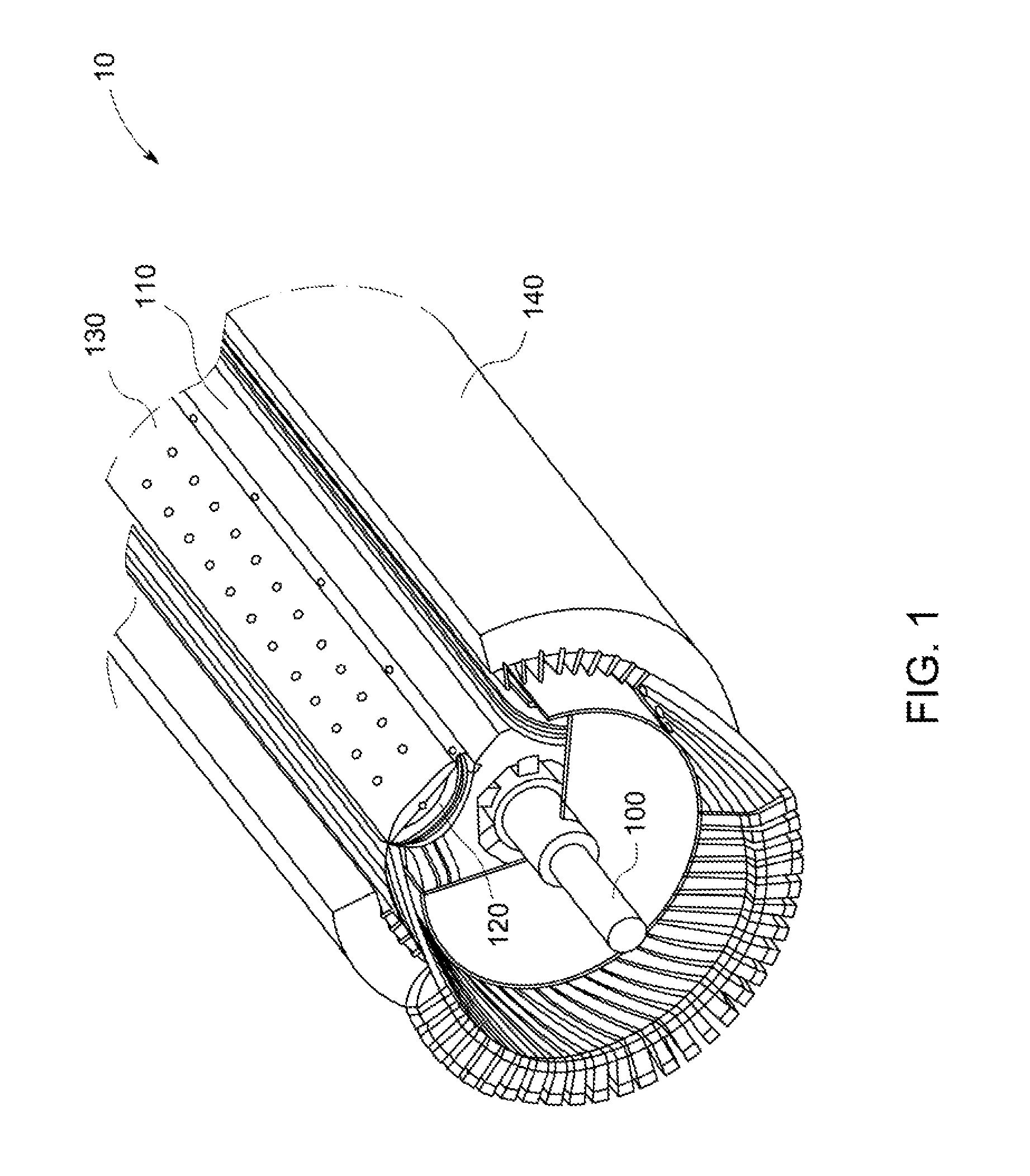
[0016]FIG. 1 illustrates a three-dimensional perspective view of a portion of a generator 10. Generator 10 may include a rotor 110 having a spindle 100 and groups of coils 120 (or windings) disposed about pole tips 130. A stator 140 is disposed about the rotor 110.

[0017]Experience has shown a generator field (e.g., a rotor) is a component that requires maintenance. This is not surprising considering that it is operating under very high centrifugal load and thermal cycling. At some point in time during the life of the generator, a rebuild of certain components may be desired. A rebuild of the field normally focuses on re-insulation of the field or rotor winding / coil. In some cases, a complete replacement of the old field may be preferred. Reliability of the generator field is increased with a rewind, as new modern insulating material can replace the original worn out insulation and address the latest service concerns. New copper coils may have a higher cross section, reducing the cur...


PUM


Abstract

A cart system is provided for a coil of a dynamoelectric machine. The cart system includes one or more support rails disposed substantially horizontally, a plurality of lifting rails disposed substantially vertically, and connected at one end to the one or more support rails, and a plurality of coil clamps for applying a compressive force. The coil clamps are attached to the lifting rails in a removable manner. The coil of the dynamoelectric machine can be placed on the cart system and the coil clamps can be arranged on the lifting rails to apply a compressive force to the coil to facilitate a testing procedure.

Description

BACKGROUND OF THE INVENTION[0001]The subject matter disclosed herein relates to a cart support system for dynamoelectric machine coils. More specifically, the subject matter disclosed herein relates to a cart support system for dynamoelectric machine coils that provides clamping means to allow testing of the coils under simulated load conditions.[0002]Dynamoelectric machines such as electrical generators conventionally include a rotor and a stator. The rotor is conventionally provided with field windings (rotor coils) that excite the generator while receiving current from an excitation source. The stator is provided with windings (or coils) from which electrical power is output. At least some known coils / windings are formed with a plurality of copper conductors that are wound to form loops. More specifically, the coils / windings are arranged in such a manner to enable a desired voltage and current characteristic to be generated during operation.[0003]Electrical insulation is wrapped ...

Claims


Application Information

Patent Timeline
Patent Type & Authority Patents(United States)
IPC IPC(8): A47B81/00B25B1/06A47B45/00
CPCH02K15/00G01R31/34H02K15/0006H02K15/14H02K15/02H02K15/04
Inventor LAPE, BROCK M.EVANS, JEFFREY D.HARBY, RICHARD A.
Owner GENERAL ELECTRIC CO
Why Eureka
Try Eureka