Display device with a brightness enhancement structure

a technology of brightness enhancement and display panel, which is applied in non-linear optics, instruments, optics, etc., can solve the problem of losing most of the brightness to the viewer, and achieve the effect of enhancing the brightness of a display panel, particularly an electrophoretic display panel

Active Publication Date: 2012-08-07
E INK CALIFORNIA
View PDF57 Cites 99 Cited by
  • Summary
  • Abstract
  • Description
  • Claims
  • Application Information

AI Technical Summary

Benefits of technology

[0003]The brightness of a display panel, particularly an electrophoretic display panel, may be enhanced through the use of an array of brightness enhancement micro-structures fabricated on top of the viewing surface of the display panel. This may be accomplished by building a structure on top of the display cells to deflect the light striking the top viewing surface. Such a structure can serve two purposes. First, it can divert the illumination light from reaching the wall of the display cells onto the reflective surface of the display panel, thus saving this light which would have otherwise been transmitted by, or absorbed into, display cell walls (i.e., an inactive part of the display panel). Secondly, without the structure on top

Problems solved by technology

Secondly, without the structure on top of the display cells, light scattered by the display panel in reflection which strikes the surface of the transparent m

Method used


Image

  • Display device with a brightness enhancement structure
  • Display device with a brightness enhancement structure
  • Display device with a brightness enhancement structure

Examples


Embodiment Construction

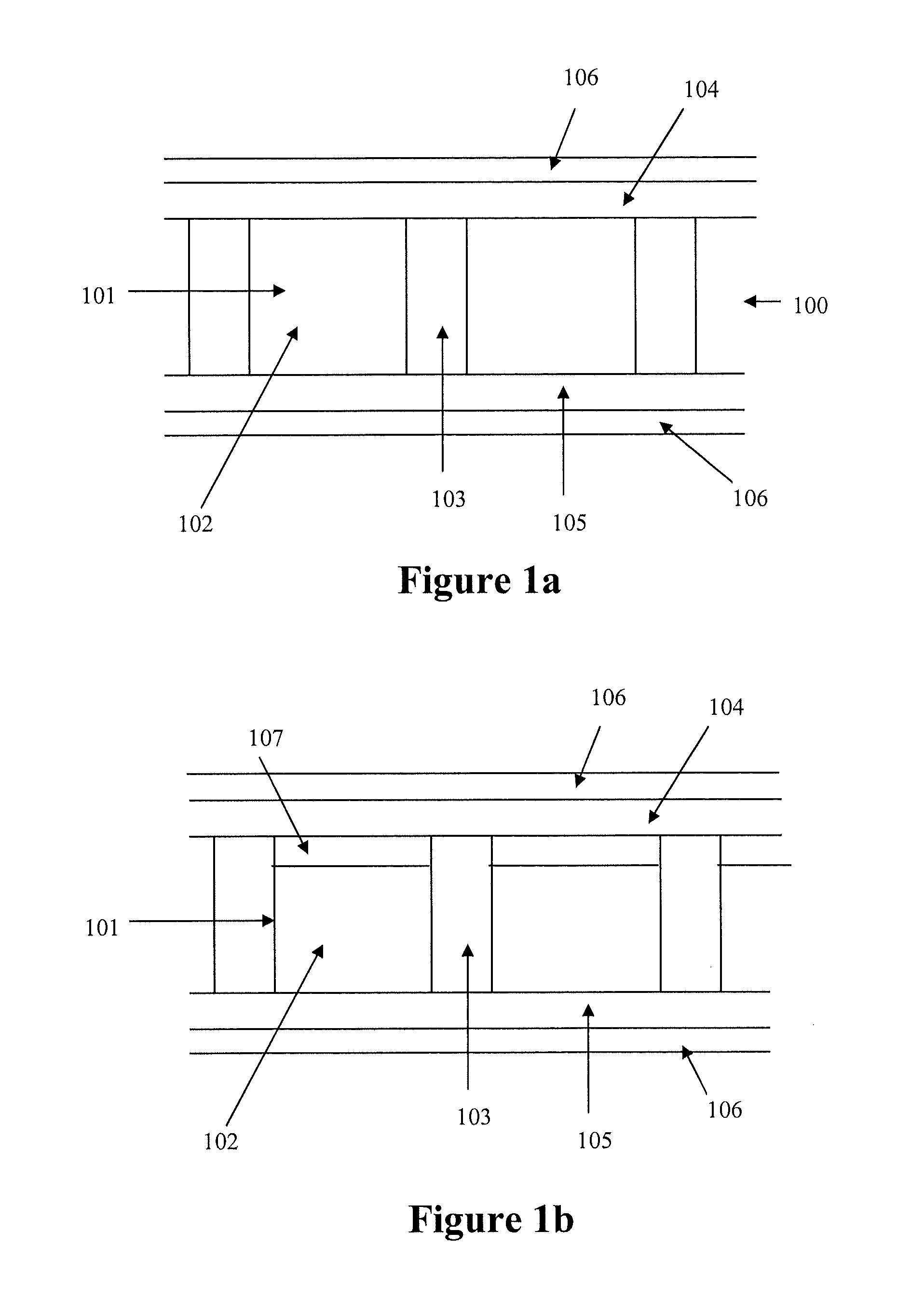
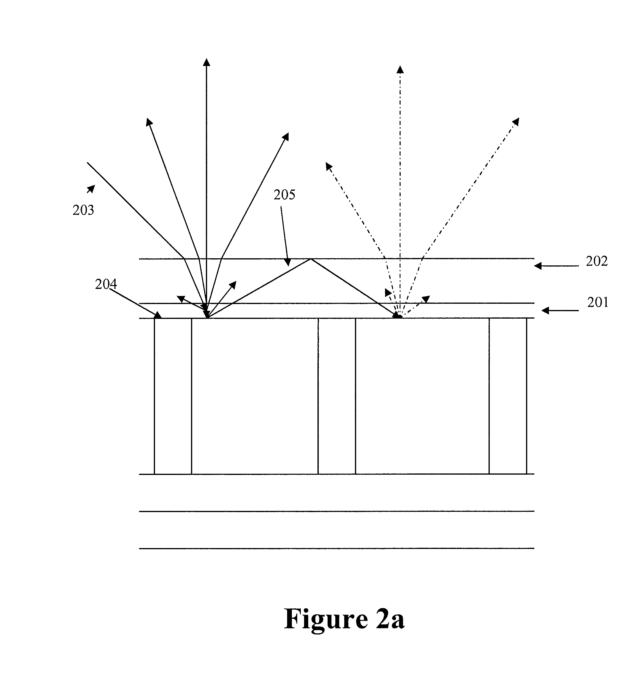
[0016]The present invention is directed to a display device which comprises (a) display cells comprising partition walls, and (b) a brightness enhancement structure comprising micro-structures, wherein said display cells are aligned with the micro-structures.

[0017]A “display device,” as used herein, refers to a device that displays images. The display devices in this application include all types of reflective display devices such as electrophoretic display devices and liquid crystal display devices. Electrophoretic display devices are preferred for this invention.

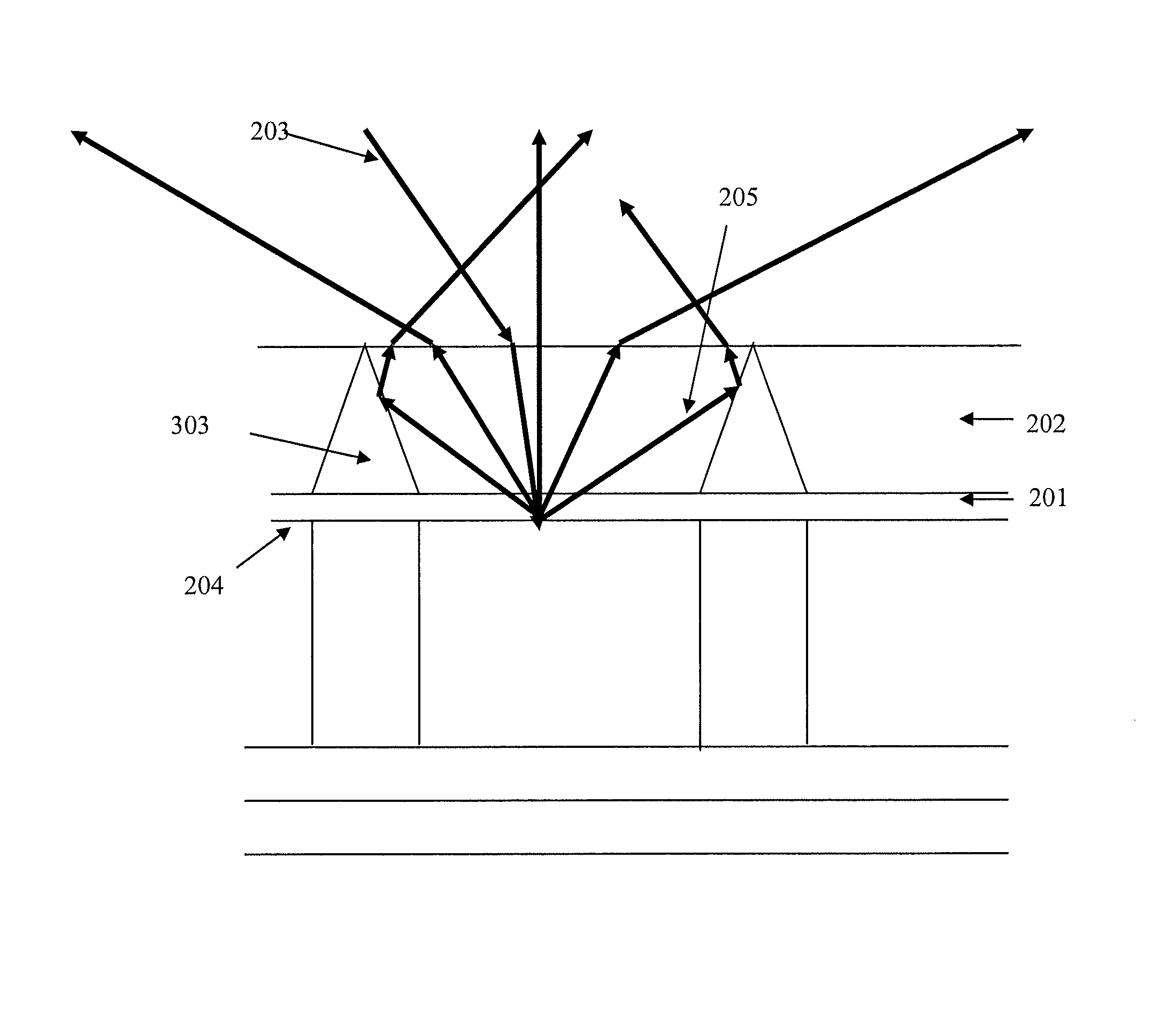
[0018]“Micro-structures” as used herein, refer to the cavities as illustrated in FIGS. 3a-3f (303), FIG. 4a (403), FIG. 5c (503), FIG. 6 (603), and FIG. 7a (703). The dimensions of the cavities (i.e., micro-structures) are illustrated in the present application. The cavities in general may have a width and height between 1-1000 microns, preferably 10-500 microns, and more preferably 20-300 microns.

[0019]FIG. 1a illustrates...


PUM


Abstract

The present invention is directed to display devices with a brightness enhancement structure comprising display cells comprising partition walls, and brightness enhancement micro-structures. The present invention is also directed to processes for the manufacture of display devices. The processes enable fabricating a display device with the micro-structures aligned with the display cells of the display device.

Description

[0001]This application claims priority to U.S. provisional application No. 60 / 991,593, filed Nov. 30, 2007; which is incorporated herein by reference in its entirety.FIELD OF THE INVENTION[0002]The present invention is directed to display devices with a brightness enhancement structure and processes for their manufacture. The processes enable fabricating a display device with brightness enhancement micro-structures aligned with the display cells of the display device.SUMMARY OF THE INVENTION[0003]The brightness of a display panel, particularly an electrophoretic display panel, may be enhanced through the use of an array of brightness enhancement micro-structures fabricated on top of the viewing surface of the display panel. This may be accomplished by building a structure on top of the display cells to deflect the light striking the top viewing surface. Such a structure can serve two purposes. First, it can divert the illumination light from reaching the wall of the display cells on...

Claims


Application Information

Patent Timeline
IPC IPC(8): G02F1/1335G02F1/1339G02F1/167G02F1/1677
CPCG02F1/133504G02F1/167G02F2001/133507G02F2001/133562G02F1/1677G02F1/133507G02F1/133562
Inventor SPRAGUE, ROBERT A.LIN, CRAIG
Owner E INK CALIFORNIA
Why Eureka
Try Eureka