Surface light source device of side light type and liquid crystal display

a surface light source and liquid crystal display technology, which is applied in the direction of lighting and heating apparatus, instruments, machines/engines, etc., can solve the problems of low electric power and low brightness of display, and achieve the effect of increasing emission

Inactive Publication Date: 2002-05-07
ENPLAS CORP +1
View PDF8 Cites 35 Cited by
  • Summary
  • Abstract
  • Description
  • Claims
  • Application Information

AI Technical Summary

Benefits of technology

The present invention is proposed under the above-described background. An object of the present invention is to provide a novel surface light source device of side light type which is capable o

Problems solved by technology

Every polarization component which does not match the transmission polarization plane is almost absorbed and

Method used


Image

  • Surface light source device of side light type and liquid crystal display
  • Surface light source device of side light type and liquid crystal display
  • Surface light source device of side light type and liquid crystal display

Examples


first embodiment

(1) First Embodiment

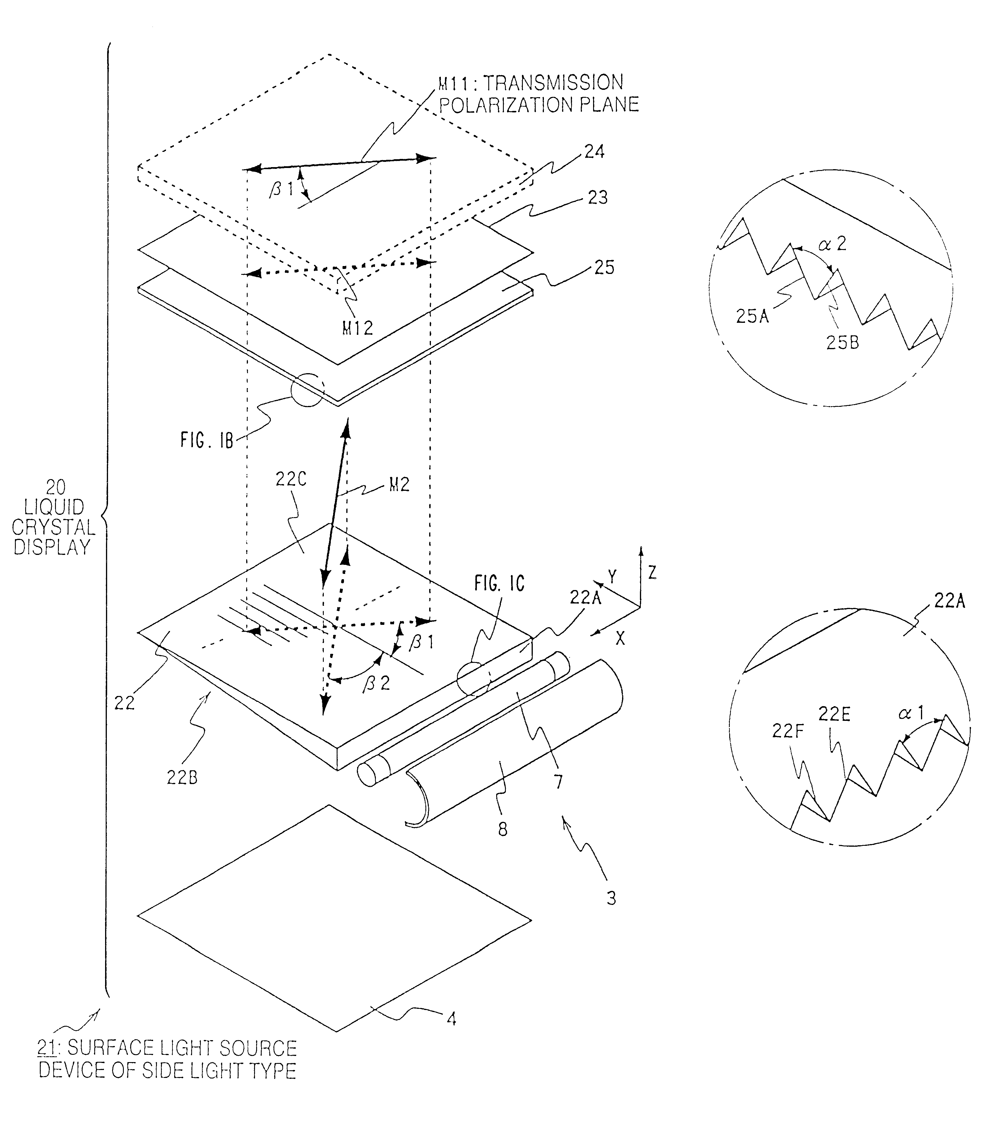
Referring to FIG. 1A, a liquid crystal display of the first embodiment in accordance with the present invention is illustrated comparatively with FIG. 11. Elements common to FIG. 11 are directed by common reference symbols and repeated descriptions of the common elements are simplified.

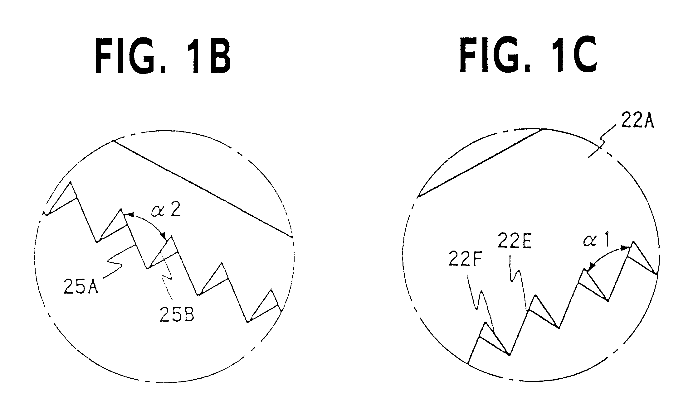
The liquid crystal display 20 includes a liquid crystal display panel 24 and a surface light source device 21 for backlighting. The surface light source device 21 comprises a primary light source 3, a reflection sheet 4, a scattering guide plate 22, a prism sheet 25, which is functioning as a light control member, and a polarization separating element 23. The reflection sheet 4, the scattering guide plate 22, the prism sheet 25 and the polarization separating element 23 are laminatedly arranged.

The primary light source 3 is disposed along a side end face (incidence face) 22A of the scattering guide plate 22. The scattering guide plate 22 includes a back face 22B and an emission fac...

second embodiment

The second embodiment is different from the first embodiment in that a surface light source device 31 arranged for backlighting employs a composite function element 32. The the following description of this embodiment is centered on the difference, with repeated explanations being omitted.

The composite function element 32 is a sheet-like member which functions both as a light control member and a polarization separating member. That is, the composite function element 32 is employed as a substitute for both the prism sheet 25 and the polarization separating member 23 which are employed in the first embodiment.

The composite function element 32 may be produced by glueing to unify a prism sheet and a polarization separating element with an optical adhesive. Orientation is set so that a prismatic surface is directed to the guide plate 22. This setting is common to that of the prism sheet 25 in the first embodiment.

The guide plate 22 is the same as in the first embodiment. A great number ...

example 1

A polarization separating element is prepared as a base material. Setting resin such as UV-setting resin is applied to one or both faces of the base material. A prismatic surface is formed by the use of setting with ultra-violet ray irradiation or the like.


PUM


Abstract

A liquid crystal display including includes a surface light source device of side light type for backlighting a liquid crystal panel. A primary light source supplies light to a guide plate. Emission from an emitting face impinges on a polarization separating element through a prism sheet. A polarization component which is directionally corresponding to a transmission polarization plane M12 is supplied to the liquid crystal panel. Reflection at the polarization separating element provides returning light which is subject to inside reflection by projection rows formed on a back face of the guide plate, thereby causing the guide plate to emit afresh recycling light. This recycling light, which is rich with the polarization component directionally in accordance with transmission polarization plane M12, impinges again on the polarization separating element. The projection rows formed on the back face run in a direction (first direction) which is generally vertical with respect to an incidence face of the guide plate while obliquely crossing with respect to both reflection polarization plane M2 and transmission polarization plane M12 of the polarization separating element. Projection rows formed on an inner face of the prism sheet run in another direction (second direction) which is generally parallel with respect to the incidence face of the guide plate. The polarization separating element and the prism sheet may be unified.

Description

1. Field of InventionThe present invention relates to a surface light source device of side light type and a liquid crystal display employing the surface light source device in its backlighting arrangement. For instance, the present invention relates to a liquid crystal display provided with a liquid crystal display panel employing TN liquid crystal.2. Related ArtSurface light source devices of side light type have been conventionally employed, for instance, to illuminate a liquid crystal display panel from its back. This arrangement is suitable for making the overall structure thin.In general, the light source device of side light type comprises a rod-shaped light source such as a cold cathode tube as a primary light source, which is arranged beside a guide plate (i.e. plate-shaped light guide). The primary light source emits illumination light which is introduced into the guide plate through a side end face (i.e. incidence face) thereof. Such introduced light propagates inside of ...

Claims


Application Information

Patent Timeline
IPC IPC(8): F21V8/00G01D11/28G02F1/13G02F1/1335G02B5/00G02F1/13357
CPCG01D11/28G02F1/13362G02B6/0053G02B6/0038G02B6/0036
Inventor ARAI, TAKAYUKIOHKAWA, SHINGO
Owner ENPLAS CORP
Why Eureka
Try Eureka