Impact detecting apparatus and package device

a technology of impact detection and package device, which is applied in the direction of apparatus for force/torque/work measurement, instruments, analysis using chemical indicators, etc., can solve the problems of unstable detection accuracy, damage to goods, and inability to d

Inactive Publication Date: 2012-08-14
RICOH KK
View PDF31 Cites 36 Cited by
  • Summary
  • Abstract
  • Description
  • Claims
  • Application Information

AI Technical Summary

Problems solved by technology

The goods may be damaged due to impact originating from inappropriate handling during the transport.
For example, they have a complicated structure, they cannot detect an impact both in a vertical direction and in a horizontal direction in a single event, and they detect only the first impact but cannot detect the second or later impacts.
On the other hand, in case of the impact detecting apparatus shown in FIG. 23A and FIG. 23B, the detection accuracy of an impact is unstable.
However, actual detection performance is not linked to the set detection levels as desired, so that the detection accuracy is often degraded.
However, in this case, the impact in the vertical direction cannot be detected.
If the object (e.g., goods) receives an impact that is stronger than an expected level due to inappropriate handling or rough handling, it is difficult to completely prevent the goods from being damaged even with use of the above impact detecting apparatuses.
If a package accommodating the goods is remarkably damaged, damage of the goods may be detected through inspection before the goods is delivered to a customer or a shop.
However, if the package is not damaged but only the goods in the package is damaged, the damage of the goods could be detected only after the goods is delivered to the customer or the shop, which leads to customer's complaint or reduction of customer's trust.

Method used


Image

  • Impact detecting apparatus and package device
  • Impact detecting apparatus and package device
  • Impact detecting apparatus and package device

Examples


first embodiment

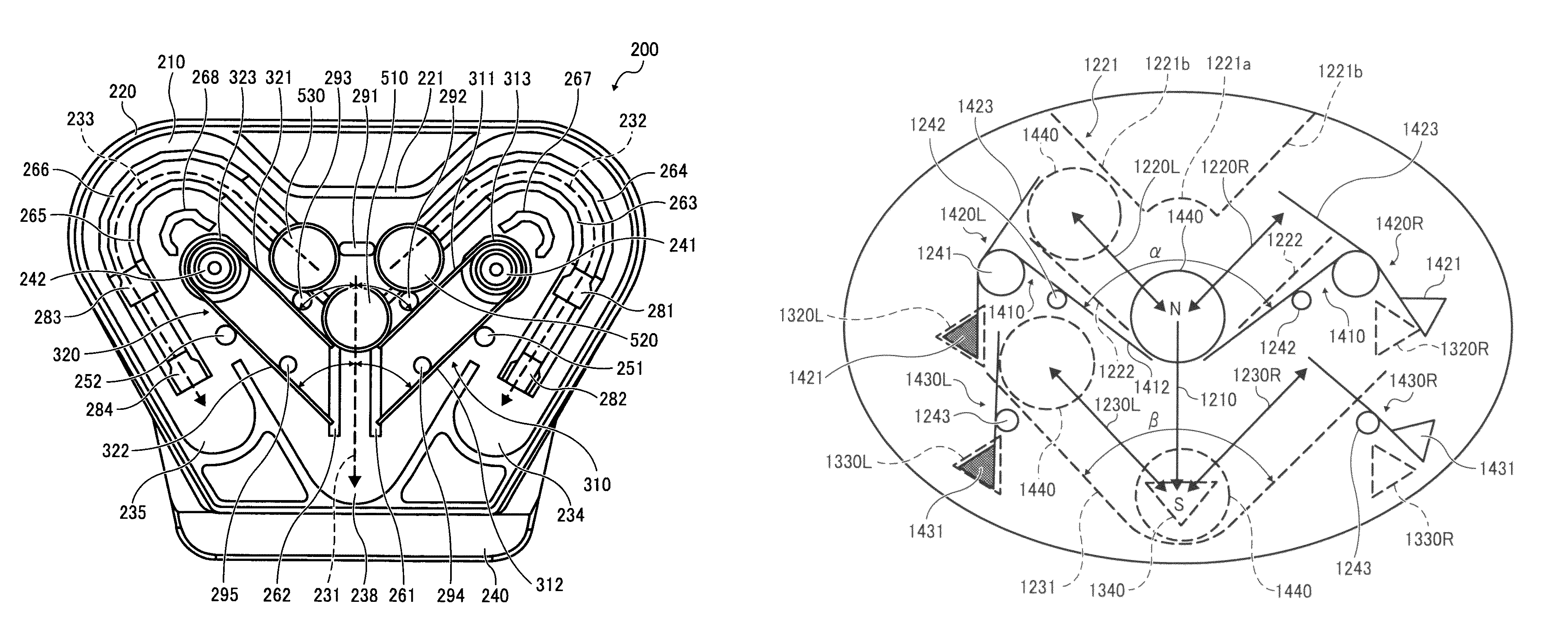
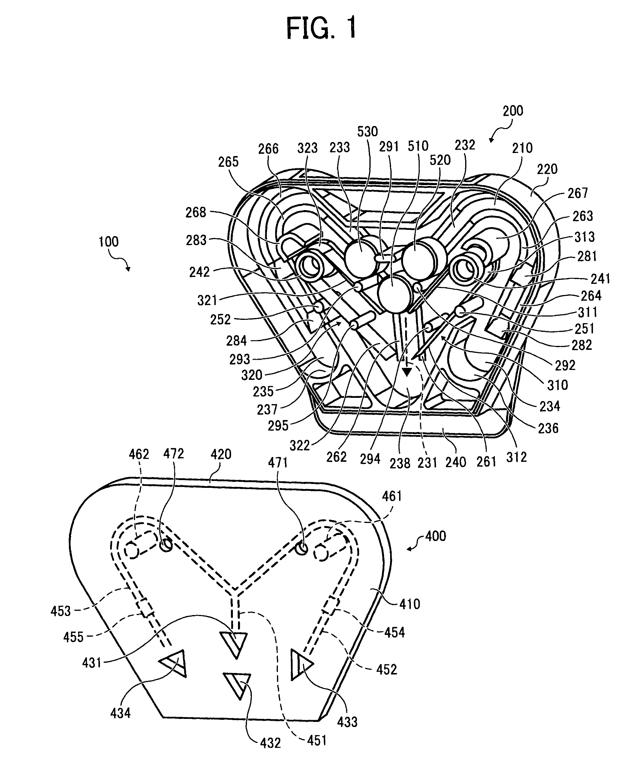
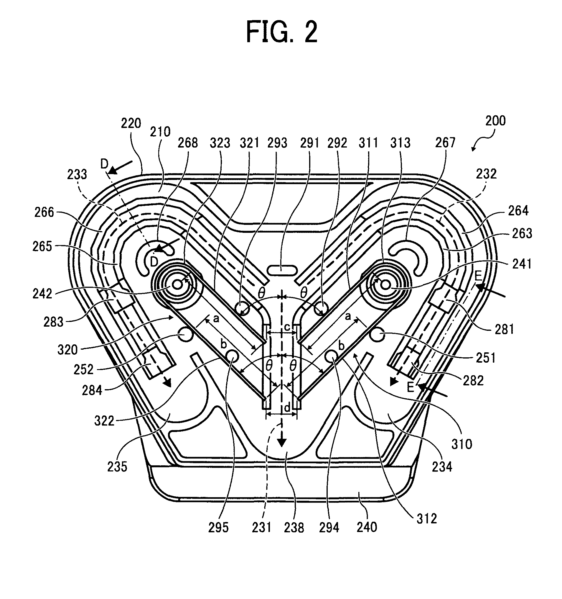
[0059]In the first embodiment, the first weight 510 is supported by a right-side plate member 310 and a left-side plate member 320 and used for detecting drop impact twice. The right-side plate member 310 is formed of a first holding member 311 as an upper part thereof, a second holding member 312 as a lower part thereof, and a U-shaped member 313 formed into a substantial U-shape and with which the first holding member 311 and the second holding member 312 are connected to each other. Similarly, the left-side plate member 320 is formed of a first holding member 321 as an upper part thereof, a second holding member 322 as a lower part thereof, and a U-shaped member 323 formed into a substantial U-shape and with which the first holding member 321 and the second holding member 322 are connected to each other. Each of the right-side plate member 310 and the left-side plate member 320 is formed by bending a single elastic thin plate made of stainless steel.

[0060]The first weight 510 is ...

second embodiment

[0110]The arm members 1420 and 1430 are described in detail below. FIG. 16A is a perspective view of the upper-side arm member 1420L. FIG. 16B is a partial enlarged plan view of the upper-side arm member 1420L. FIG. 16C is a partial enlarged front view of the upper-side arm member 1420L. FIG. 16D is an enlarged perspective view of the upper-side arm member 1420L. FIGS. 17A to 17C are schematic diagrams of operational states of the display portion 1421 according to the FIG. 18 is a schematic diagram for explaining a dimensional relation of components of the arm member 1420. While the upper-side arm members 1420L and 1420R are bilaterally symmetric to each other, the configurations thereof are the same to each other. Furthermore, the configurations of the lower-side arm members 1430L and 1430R are the same as those of the upper-side arm members 1420L and 1420R. Therefore, only the configuration of the upper-side arm member 1420L is described in detail below. As shown in FIG. 16A, the...


PUM

PropertyMeasurementUnit
thicknessaaaaaaaaaa
widthaaaaaaaaaa
effective lengthaaaaaaaaaa

Abstract

An impact detecting apparatus that is configured to be attached to an object and includes a drop-impact display unit configured to display a direction of drop impact when the object is dropped; and a tilt display unit configured to display a direction of tilting when the object is tilted. The drop-impact display unit and the tilt display unit displays the direction of drop impact and the direction of tilting at the same time.

Description

CROSS-REFERENCE TO RELATED APPLICATIONS[0001]The present application claims priority to and incorporates by reference the entire contents of Japanese Patent Application No. 2008-223828 filed in Japan on Sep. 1, 2008 and Japanese Patent Application No. 2008-299992 filed in Japan on Nov. 25, 2008.BACKGROUND OF THE INVENTION[0002]1. Field of the Invention[0003]The present invention relates to a technology for detecting whether an object has been subjected to drop impact or tilted.[0004]2. Description of the Related Art[0005]Goods including precision apparatuses are typically transported for long / short distances with various transportation media such as trucks, trains, ships. The goods may be damaged due to impact originating from inappropriate handling during the transport. Damage of the goods caused by impact of a predetermined level or smaller can be prevented by making a prior assessment on the goods accommodated in a package and taking a countermeasure against the damage based on a...

Claims


Application Information

Patent Timeline
Patent Type & Authority Patents(United States)
IPC IPC(8): G01L5/00G01N3/30
CPCB65D79/02G01C9/10G01P15/036G01P15/122
Inventor NARUISHI, MOKU
Owner RICOH KK
Why Eureka
Try Eureka