Electroconductive fine particles, anisotropic electroconductive material, and electroconductive connection structure

a technology of anisotropic electroconductive material and fine particles, which is applied in the field of fine particles, can solve the problems of difficult to improve the packaging density of the ic or the lsi by using soldering, and the failure of the soldering to connect the ic or the lsi to the printed substrate efficiently, and achieves the effect of avoiding disconnection and avoiding disconnection

Inactive Publication Date: 2010-05-06
SEKISUI CHEM CO LTD
View PDF5 Cites 18 Cited by
  • Summary
  • Abstract
  • Description
  • Claims
  • Application Information

AI Technical Summary

Benefits of technology

[0106]According to the present invention, it is possible to provide: a conductive fine particle which is used for conductive connection between fine electrodes and is less likely to have a crack in a solder layer nor breakage in a connection interface between an electrode and the conductive fine particle even with a drop impact and the like, and is less likely to have fatigue even after repetitive heating and cooling; an anisotropic conductive material obtained by using the conductive fine particle; and a conductive connection structure.

Problems solved by technology

However, soldering has failed to connect the IC or the LSI to the printed substrate efficiently.
Furthermore, it has been hard to improve the packaging density of the IC or the LSI by using soldering.
However, since multi-layering of a substrate has been developed in recent years and a multilayer substrate is vulnerable to an effect of usage environment, there has been a problem that disconnection tends to occur due to the stress and strain appearing in the substrates.
As a result, there has been a case where a crack occurs in the solder ball and disconnection is caused.
However, when the conductive fine particle, in which a solder layer is formed on the surface of a resin fine particle, is used in electronic device such as a cell-phone, there has been an issue where a drop impact and the like causes a crack in the solder layer or breakage in a connection interface between the electrode and the conductive fine particle.
There has been a problem that the crack in the solder layer and breakage in the connection interface causes disconnection between the electrode and the conductive fine particle.
However, when the electrodes on the substrates are conductively connected with use of the conductive fine particle disclosed in Patent Document 1, there has been a case where a solder layer is melted in the process 1 and the solder layer adequate for conductively connecting the electrode on the second substrate is not left on the surface of the metal layer of the conductive fine particle.
As a result, there has been a case where conductive connection is not allowed.
Repetition of this heat cycle may have caused a case where thermal fatigue occurs in the solder layer and the connection interface of the electrode and the conductive fine particle is destroyed, so that disconnection is caused.

Method used


Image

  • Electroconductive fine particles, anisotropic electroconductive material, and electroconductive connection structure
  • Electroconductive fine particles, anisotropic electroconductive material, and electroconductive connection structure
  • Electroconductive fine particles, anisotropic electroconductive material, and electroconductive connection structure

Examples


example 1

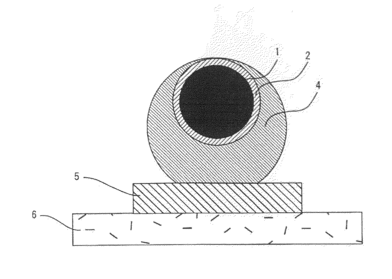
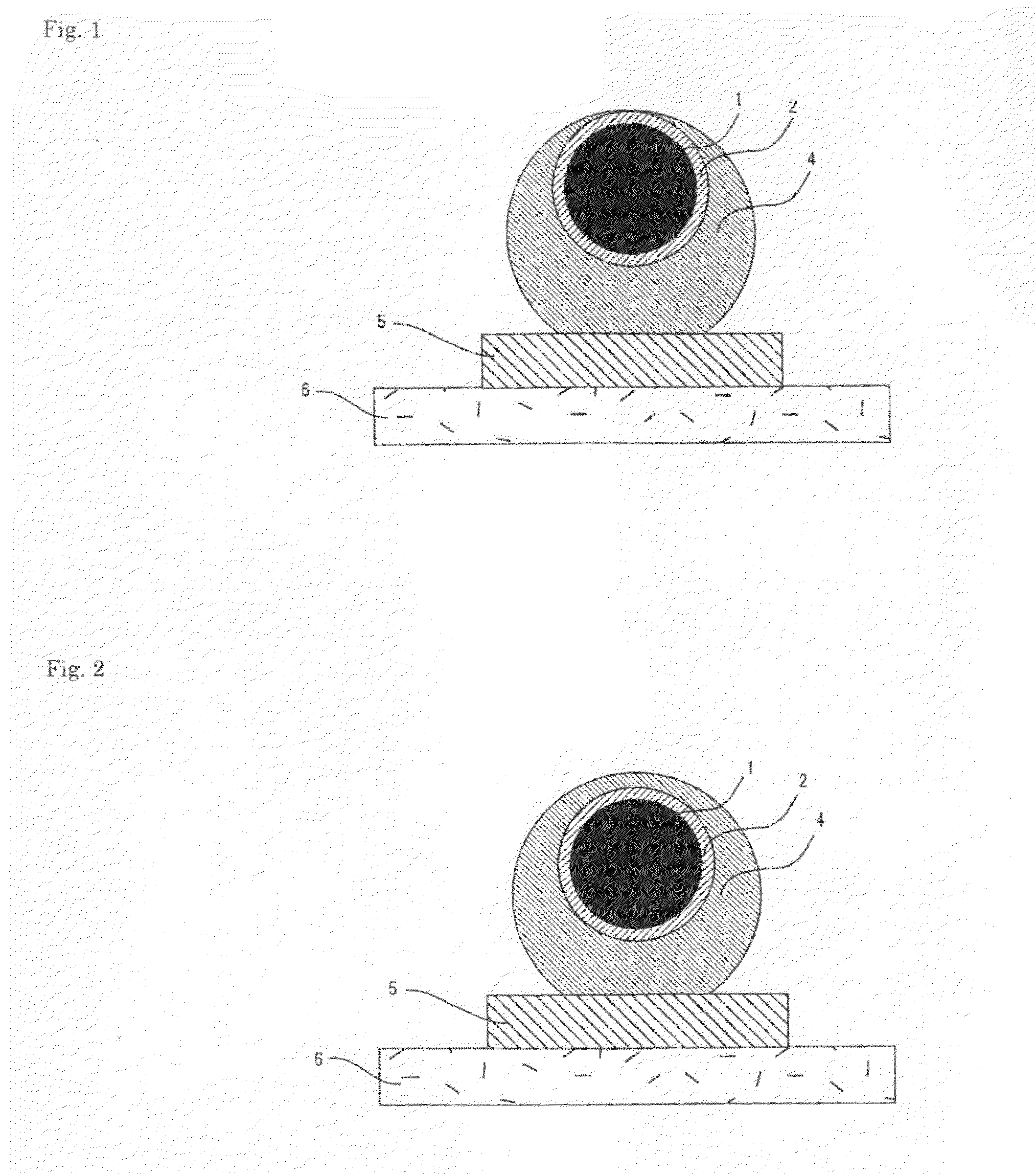
(1) Production of Resin Fine Particle

[0108]An amount of 50 parts by weight of divinylbenzene and an amount of 50 parts by weight of tetramethyrolmethane tetraacrylate were copolymerized so that a resin fine particle (average particle diameter of 240 μm, CV value of 0.42%) was produced.

(2) Production of Conductive Fine Particle

[0109]Electroless nickel plating was carried out on the obtained resin fine particle to form a base nickel plating layer having a thickness of 0.3 μm on the surface of the resin fine particle. Subsequently, nickel electroplating was carried out on the resin fine particle with the base nickel plating layer formed thereon, so that the thickness of the base nickel plating layer became 5 μm. By further carrying out gold immersion plating, a gold layer having a thickness of 2 μm was formed. Furthermore, by carrying out electroplating, a solder layer, which has a thickness of 25 μm and contains tin and silver, was formed. Next, the electroplating solution was filtrat...
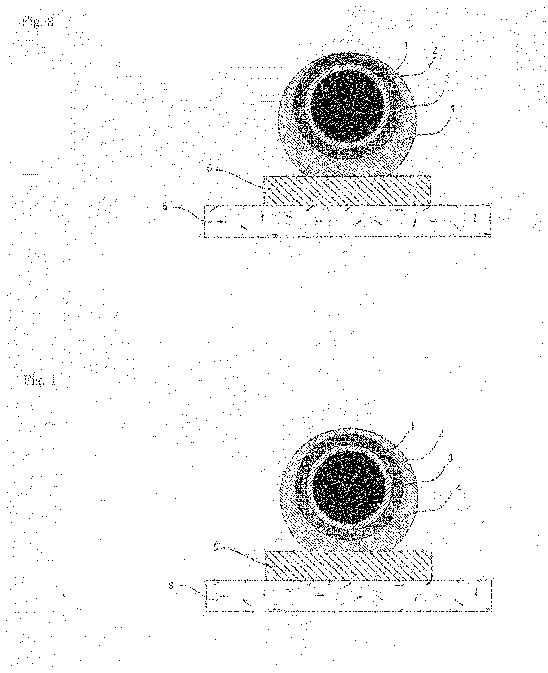
example 2

[0119]Electroless nickel plating was carried out on the resin fine particle produced in Example 1 and a base nickel plating layer having a thickness of 0.3 μm was formed on the surface of the resin fine particle. Then, copper electroplating was carried out on the resin fine particle, in which the base nickel plating layer was formed, and a copper layer having a thickness of 10 μm was formed. Further, by carrying out electroplating, a solder layer, which has a thickness of 25 μm and contains tin and silver, was formed. Subsequently, the electroplating solution was filtrated, and the obtained particle was washed with water and then dried in the vacuum dryer at a temperature of 50° C. Thus, the conductive fine particle was obtained, in which a copper layer and a solder layer were sequentially formed on the surface of the resin fine particle.

[0120]An amount of 1.5 g of the conductive fine particle, in which a copper layer and a solder layer were sequentially formed on the surface of the...

example 3

[0122]A conductive fine particle, in which nickel was adhered to the surface of the solder layer, was obtained in the same manner as in Example 2, except that the solution temperature of the electroless nickel plating solution was changed to 40° C. and the plating reaction time was changed to eight minutes. An average particle diameter of the conductive fine particles was 310 μm and a CV value was 1.02%.

[0123]The conductive fine particle, in which nickel was adhered to the surface of the solder layer, was analyzed with use of a fluorescent X-ray analyzer (EDX-800HS, produced by SHIMADZU CORPORATION) to find that the contents of the respective metals were 1.2% by weight of silver and 0.2% by weight of nickel, with the remainder being tin, with respect to the total of the metal contained in the solder layer and the adhered nickel.


PUM

PropertyMeasurementUnit
diameteraaaaaaaaaa
conductiveaaaaaaaaaa
weightaaaaaaaaaa

Abstract

It is an object of the present invention to provide: a conductive fine particle, which is used for conductive connection between fine electrodes and tends not to give rise to a crack in the solder layer or disconnection caused by breakage in the connection interface between an electrode and the conductive fine particle even with a drop impact and the like, and tends not to have fatigue even after repetitive heating and cooling; an anisotropic conductive material obtained by using the conductive fine particle; and a conductive connection structure.
The present invention relates to a conductive fine particle, which comprises a solder layer containing tin and being formed on a surface of a resin fine particle, with nickel adhered to a surface of the solder layer, and contains 0.0001 to 5.0% by weight of the nickel with respect to a total of a metal contained in the solder layer and the nickel adhered to the surface of the solder layer.

Description

TECHNICAL FIELD[0001]The present invention relates to a conductive fine particle which is used for conductive connection between fine electrodes. More specifically, the present invention relates to a conductive fine particle, which tends not to give rise to a crack in the solder layer or disconnection caused by breakage in the connection interface between an electrode and the conductive fine particle even with a drop impact and the like, and tends not to have fatigue even after repetitive heating and cooling. Further, the present invention relates to an anisotropic conductive material obtained by using the conductive fine particle, and a conductive connection structure.BACKGROUND ART[0002]Conventionally, integrated circuits (IC), or large-scale integrated circuits (LSI) have been connected to a printed substrate by soldering process. However, soldering has failed to connect the IC or the LSI to the printed substrate efficiently. Furthermore, it has been hard to improve the packaging...

Claims


Application Information

Patent Timeline
Patent Type & Authority Applications(United States)
IPC IPC(8): B32B15/02
CPCB23K35/262C23C18/1635C23C18/1653C23C18/1692C23C18/30C23C18/34C23C18/54H01L24/29H01L2924/01005H01L2924/01013H01L2924/01015H01L2924/01025H01L2924/01027H01L2924/01029H01L2924/0103H01L2924/01046H01L2924/01047H01L2924/01049H01L2924/0105H01L2924/01051H01L2924/01073H01L2924/01078H01L2924/01079H01L2924/01327H01L2924/04941H01L2924/10253H01L2924/14H01R13/03H05K3/323H05K2201/0221H05K2203/0425H01L2924/01023H01L2224/2919H01L2924/01006H01L2924/01019H01L2924/01033H01L2924/014H01L2924/0665H01L2224/29101H01L2924/0132H01L2924/0133H01L2924/0134H01L2224/29111H01L2224/2939H01L2224/29311H01L2224/29411H01L2924/07811B23K2101/36Y10T428/2982H01L2924/181Y10T428/2998H01L2924/00H01L2924/01028H01L2924/00012H01L2924/00014H01L2924/3512
Inventor SUN, REN-DEMATSUSHITA, KIYOTOSASAKI, TAKUUENOYAMA, SHINYAOKUDA, MASAKIOKINAGA, NOBUYUKI
Owner SEKISUI CHEM CO LTD
Why Eureka
Try Eureka