Lead-Free Solder Alloys And Solder Joints Thereof With Improved Drop Impact Resistance

a technology of lead-free solder alloys and solder joints, which is applied in the field of lead-free solder alloy compositions, can solve the problems of fragile solder joints made from these recommended sn—ag—cu alloys, prone to premature interfacial failure, and the drop test performance of these alloys is still inferior to that of eutectic tin-lead, and achieves the effect of improving the drop impact resistan

Active Publication Date: 2007-06-14
INDIUM CORPORATION
View PDF2 Cites 18 Cited by
  • Summary
  • Abstract
  • Description
  • Claims
  • Application Information

AI Technical Summary

Benefits of technology

[0005] Lead-free solder alloys and solder joints thereof with improved drop impact resistance are disclosed. In one particular exemplary embodiment, the lead-free solder alloys preferably comprise 0.0-4.0 wt. % of Ag, 0.01-1.5 wt. % of Cu, at least one of the following additives: Mn in an amount of 0.001-1.0 wt. %, Ce in an amount of 0.001-0.8 wt. %, Y in an amount of 0.001-1.0 wt. %, Ti in an amount of 0.001-0.8 wt. %, and Bi in an amount of 0.01-1.0 wt. %, and the remainder of Sn.

Problems solved by technology

However, recent investigations on the lead-free solder alloys have shown that solder joints made from these recommended Sn—Ag—Cu alloys may be fragile and prone to premature interfacial failure under drop impact loading.
Although reduction of Ag content in Sn—Ag—Cu alloys has been found to be helpful, drop test performance for these alloys is still inferior to that of eutectic tin-lead.

Method used


Image

  • Lead-Free Solder Alloys And Solder Joints Thereof With Improved Drop Impact Resistance
  • Lead-Free Solder Alloys And Solder Joints Thereof With Improved Drop Impact Resistance
  • Lead-Free Solder Alloys And Solder Joints Thereof With Improved Drop Impact Resistance

Examples


Embodiment Construction

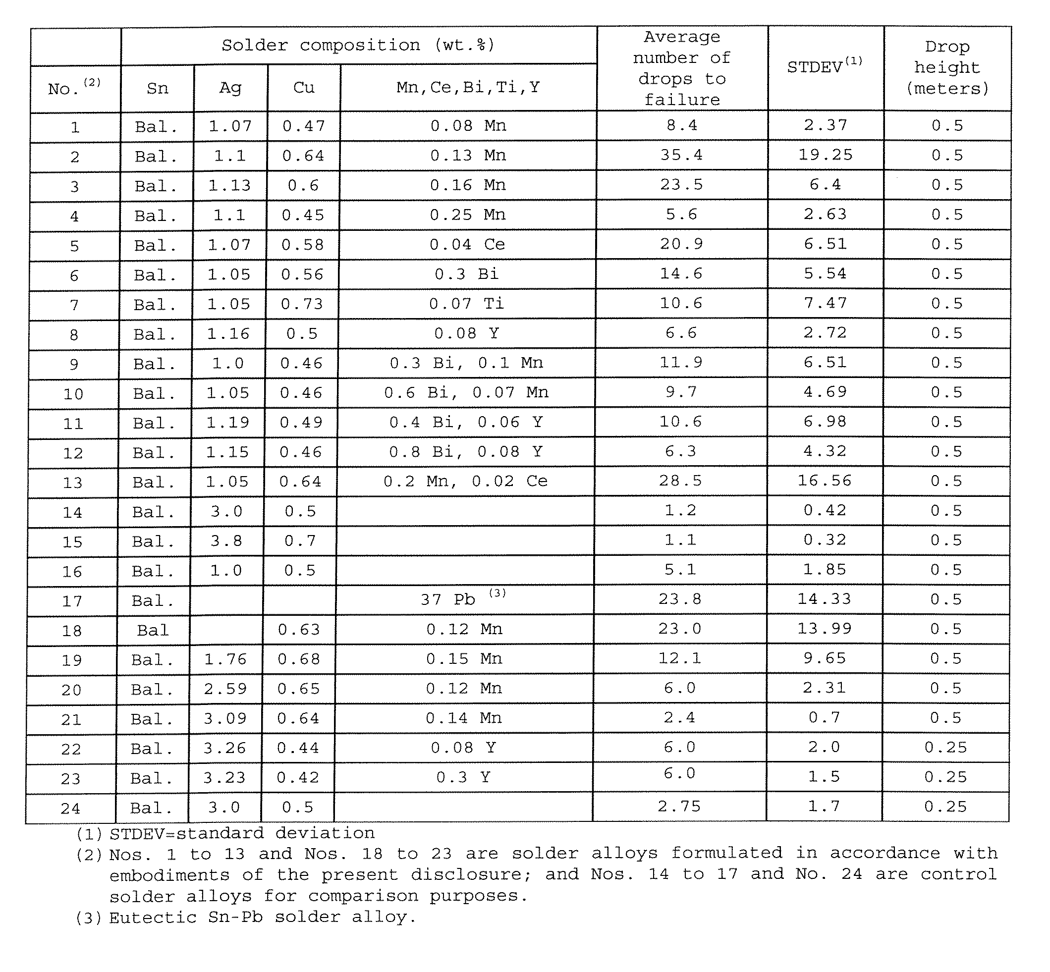
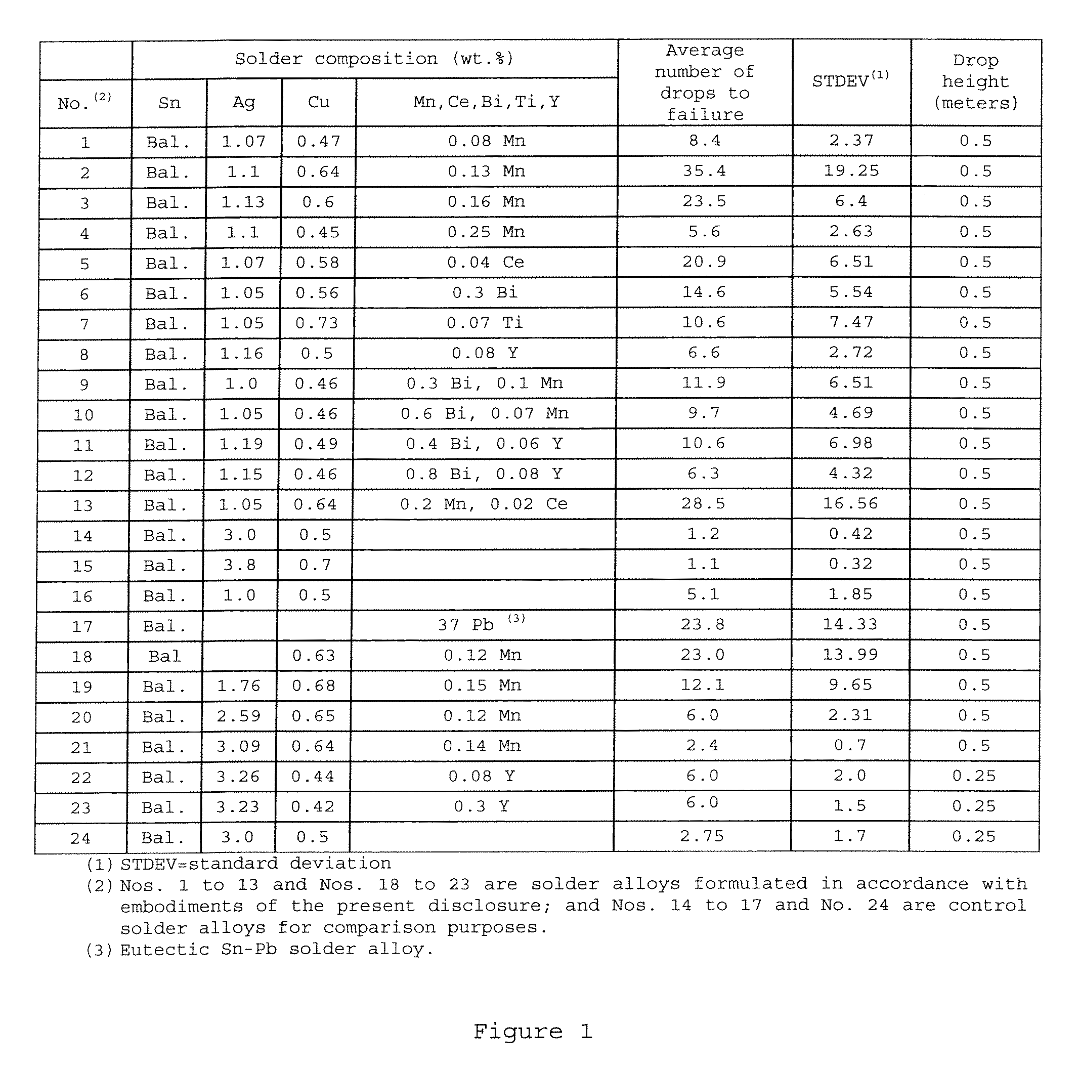
[0027] The present disclosure relates to Sn—Ag—Cu based (i.e., lead-free) solder alloys and solder joints thereof with improved drop impact reliability. The disclosed Sn—Ag—Cu based solder alloys preferably comprise 0.0-4.0 wt. % of Ag, 0.01-1.5 wt. % of Cu, at least one of the following additives: Mn in an amount of 0.001-1.0 wt. %, Ce in an amount of 0.001-0.8 wt. %, Y in an amount of 0.001-1.0 wt. %, Ti in an amount of 0.001-0.8 wt. %, and Bi in an amount of 0.01-1.0 wt. %, and the remainder of Sn.

[0028] Solder joints made of the above-described lead-free solder alloys have a higher drop impact resistance, compared to those made of the conventional Sn—Ag—Cu solder alloys that have been recommended and are currently in use in the industry.

[0029] The disclosed Sn—Ag—Cu based solder alloys are particularly suitable for, but not limited to, producing solder bumps such as those in ball grid array (BGA) packages which require high drop impact reliability especially when used in mobil...


PUM

PropertyMeasurementUnit
massaaaaaaaaaa
temperatureaaaaaaaaaa
diameteraaaaaaaaaa

Abstract

Lead-free solder alloys and solder joints thereof with improved drop impact resistance are disclosed. In one particular exemplary embodiment, the lead-free solder alloys preferably comprise 0.0-4.0 wt. % of Ag, 0.01-1.5 wt. % of Cu, at least one of the following additives: Mn in an amount of 0.001-1.0 wt. %, Ce in an amount of 0.001-0.8 wt. %, Y in an amount of 0.001-1.0 wt. %, Ti in an amount of 0.001-0.8 wt. %, and Bi in an amount of 0.01-1.0 wt. %, and the remainder of Sn.

Description

CROSS-REFERENCE TO RELATED APPLICATIONS [0001] This patent application claims priority to U.S. Provisional Patent Application No. 60 / 749,615, filed Dec. 13, 2005, which is hereby incorporated by reference herein in its entirety.FIELD OF THE DISCLOSURE [0002] The present disclosure relates generally to lead-free solder alloy compositions for use in electronics and, in particular, to lead-free solder alloys and solder joints thereof with improved drop impact resistance. BACKGROUND OF THE DISCLOSURE [0003] Among the various lead-free solder alloy choices as replacements of conventional tin-lead solders, Tin (Sn)-Silver (Ag)-Copper (Cu) alloys are currently the most popular because of their relatively good soldering performance, excellent creep resistance, and thermal fatigue reliability, as well as their compatibility with the current components. A variety of Sn—Ag—Cu solder alloys have been proposed and recommended for use by industrial organizations in different countries. For exampl...

Claims


Application Information

Patent Timeline
Patent Type & Authority Applications(United States)
IPC IPC(8): C22C13/00
CPCC22C13/02C22C13/00
Inventor LIU, WEIPINGLEE, NING-CHENG
Owner INDIUM CORPORATION
Why Eureka
Try Eureka