actuator

A technology for actuators and moving bodies, which can be applied to electric components, fluids that use vibration, and parts of transformers/inductors, and can solve problems such as coil wire breakage

Active Publication Date: 2022-03-22
SANKYO SEIKI MFG CO LTD
View PDF19 Cites 0 Cited by
  • Summary
  • Abstract
  • Description
  • Claims
  • Application Information

AI Technical Summary

Problems solved by technology

However, in the actuator described in Patent Document 1, since the power supply board is fixed to the case, the impact when dropped is transmitted to the power supply board through the case.
At this time, if the power supply board moves in a direction away from the coil, the coil wire is stretched and the coil wire is likely to be disconnected near the place where the coil wire is soldered to the power supply board.

Method used


Image

  • actuator
  • actuator
  • actuator

Examples


other Embodiment approach

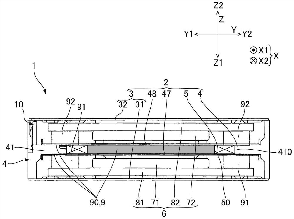
[0101] In the above-mentioned embodiment, the permanent magnets (the first permanent magnet 71 and the second permanent magnet 72) are provided on both sides of the first direction Z relative to the coil 5, but it is also possible to apply the present invention to One side of the first direction Z of 5 is provided with an actuator of a permanent magnet.

[0102] In the above-mentioned embodiment, the coil holder 4 and the coil 5 are provided on the support body 2, and the permanent magnets (the first permanent magnet 71 and the second permanent magnet 72) and the yokes (the first yoke 81 and the second The yoke 82) is provided on the movable body 6. However, the structure using the first plate 47 and the second plate 48 or the structure for providing slack on the power supply substrate 10 can also be applied to provide the coil holder 4 and the coil 5 on the movable body 6, and permanently The magnets (the first permanent magnet 71 and the second permanent magnet 72 ) and the...


PUM


Abstract

The present invention provides an actuator capable of preventing disconnection of a coil wire connected to a power supply substrate, thereby improving drop impact resistance. In the actuator (1), the power supply substrate (10) to which the coil wires (56, 57) are connected is held on the coil holder (4) covered by the case (3), so that the impact when falling is not easy It propagates to the power supply substrate (10) via the housing (3). In addition, even in the case of the shock propagation when falling, since the power supply substrate (10) moves together with the coil holder (4), the situation that the coil wires (56, 57) are stretched is less likely to occur. Therefore, since the coil wires (56, 57) are less likely to be disconnected due to the impact of the drop, the drop impact resistance performance can be improved. In addition, in the coil holder (4), the power supply substrate (10) is provided at a position separated from the contact portion with the movable body (6). Therefore, even if the movable body (6) comes into contact with the contact portion of the coil holder (4), the impact at this time does not easily propagate to the power supply board (10).

Description

technical field [0001] The present invention relates to an actuator that vibrates a movable body. Background technique [0002] As a device for notifying information by vibration, an actuator is proposed, which includes: a movable body with a permanent magnet, a support body with a coil facing the permanent magnet, and a coil holder for holding the coil on the support body. frame, a case covering the movable body and the coil holder, and a power supply substrate to which coil wires constituting the coil are connected (see Patent Document 1). In the actuator described in Patent Document 1, the power supply substrate is fixed to the case so as to protrude from the case. [0003] When the actuator described in Patent Document 1 is incorporated in a device such as a remote controller or a game controller, the device may drop, so high drop impact resistance is required. However, in the actuator described in Patent Document 1, since the power supply board is fixed to the case, t...

Claims


Application Information

Patent Timeline
Patent Type & Authority Patents(China)
IPC IPC(8): H02K33/18
CPCH02K33/18B06B1/045H01F27/2823H01F27/2828H01F27/325H02K33/16H02K5/04H01F27/2866
Inventor 森亮北原裕士
Owner SANKYO SEIKI MFG CO LTD
Why Eureka
Try Eureka