Supercharge Your Innovation With Domain-Expert AI Agents!

Tire tread skiving machine

a tire tread and skiving machine technology, which is applied in the direction of sawing apparatus, tires, domestic applications, etc., can solve the problems of cannot be dynamically varied, excessive tire wear, and fixed angle of cut through tire tread extrusion

Inactive Publication Date: 2012-08-21
BRAZIER PAUL
View PDF5 Cites 4 Cited by
  • Summary
  • Abstract
  • Description
  • Claims
  • Application Information

AI Technical Summary

Benefits of technology

"The present invention provides a tire tread skiving machine that overcomes the disadvantages of previous machines. The machine has a frame with two ends and a cutting platen that extends between the ends. There are also infeed and outfeed conveyors that move the tire tread extrusion perpendicular to the cutting platen and cut the tire tread. A rail assembly is mounted on the frame and a carriage is movably mounted on the rail assembly. A rotatably driven skiving blade is mounted on the carriage and contacts the tire tread extrusion as the carriage moves along the cutting platen. The rail assembly can be pivoted to change the angle of cut and is dynamically adjustable. The technical effects of this invention are improved precision and flexibility in the skiving process, resulting in better quality tire treads."

Problems solved by technology

One difficulty of these previously known machines for cutting tire treads from a synthetic rubber extrusion is that the angle of the cut through the extrusion is fixed and cannot be dynamically varied.
While that fixed angle is satisfactory for many automotive vehicle tire applications, in some cases, a fixed angle of the cut through the tire tread extrusion is unacceptable.
This “speed bump” can result not only in excessive tire wear, but also undesirable vibration in the vehicle.
A still further disadvantage of these previously known tire tread skiving machines is that the tire tread extrusion is extremely tacky following the extruding operation.

Method used


Image

  • Tire tread skiving machine
  • Tire tread skiving machine
  • Tire tread skiving machine

Examples


Embodiment Construction

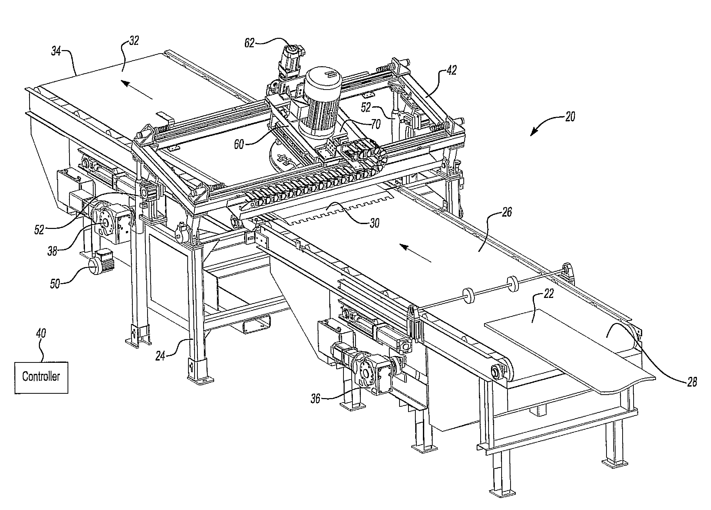
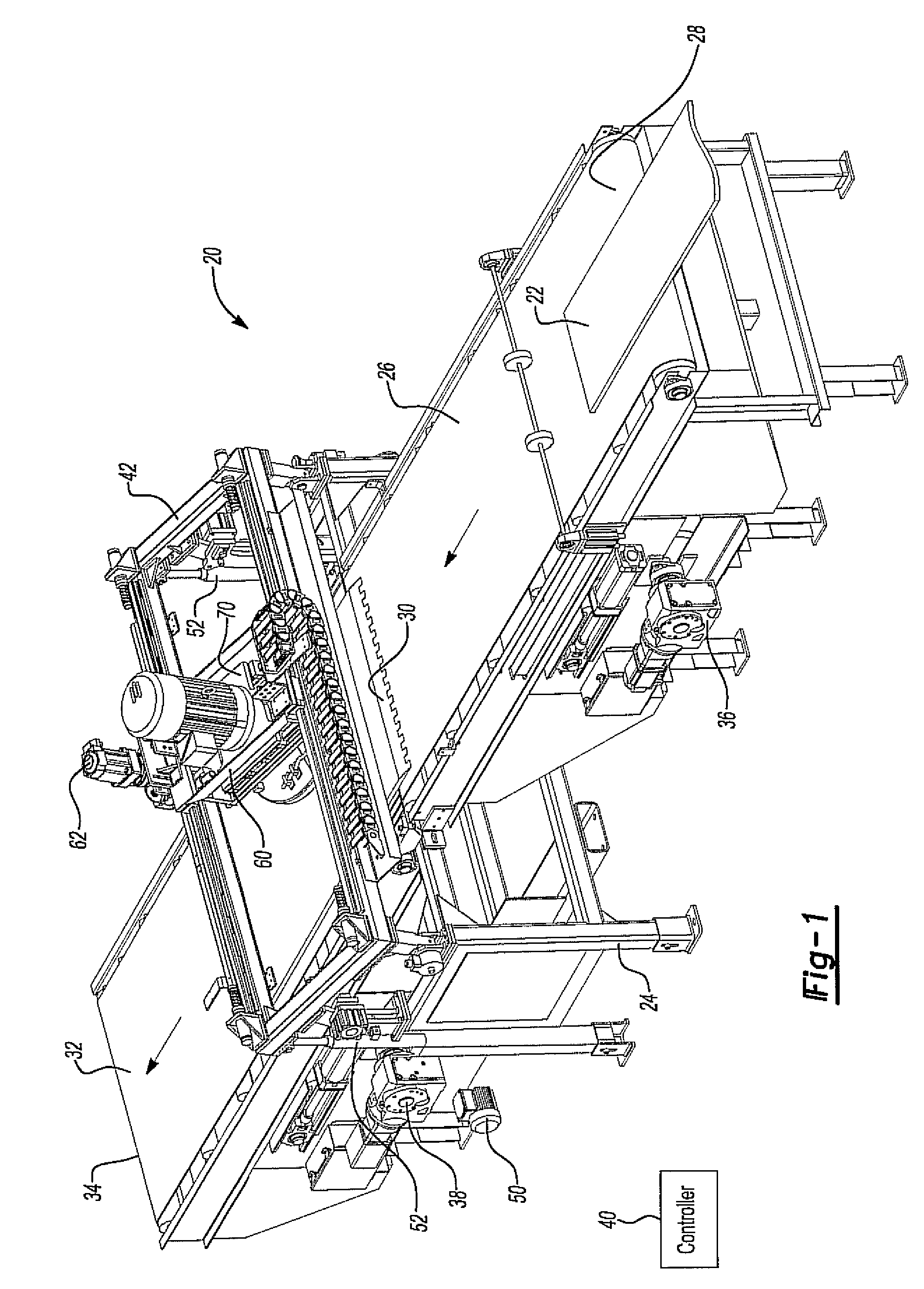
[0026]With reference first to FIG. 1, a preferred embodiment of a tire tread skiving machine 20 is shown for cutting tire treads from a tire tread extrusion 22. The tire tread extrusion 22 is typically constructed of a synthetic rubber, although other materials may alternatively be used.

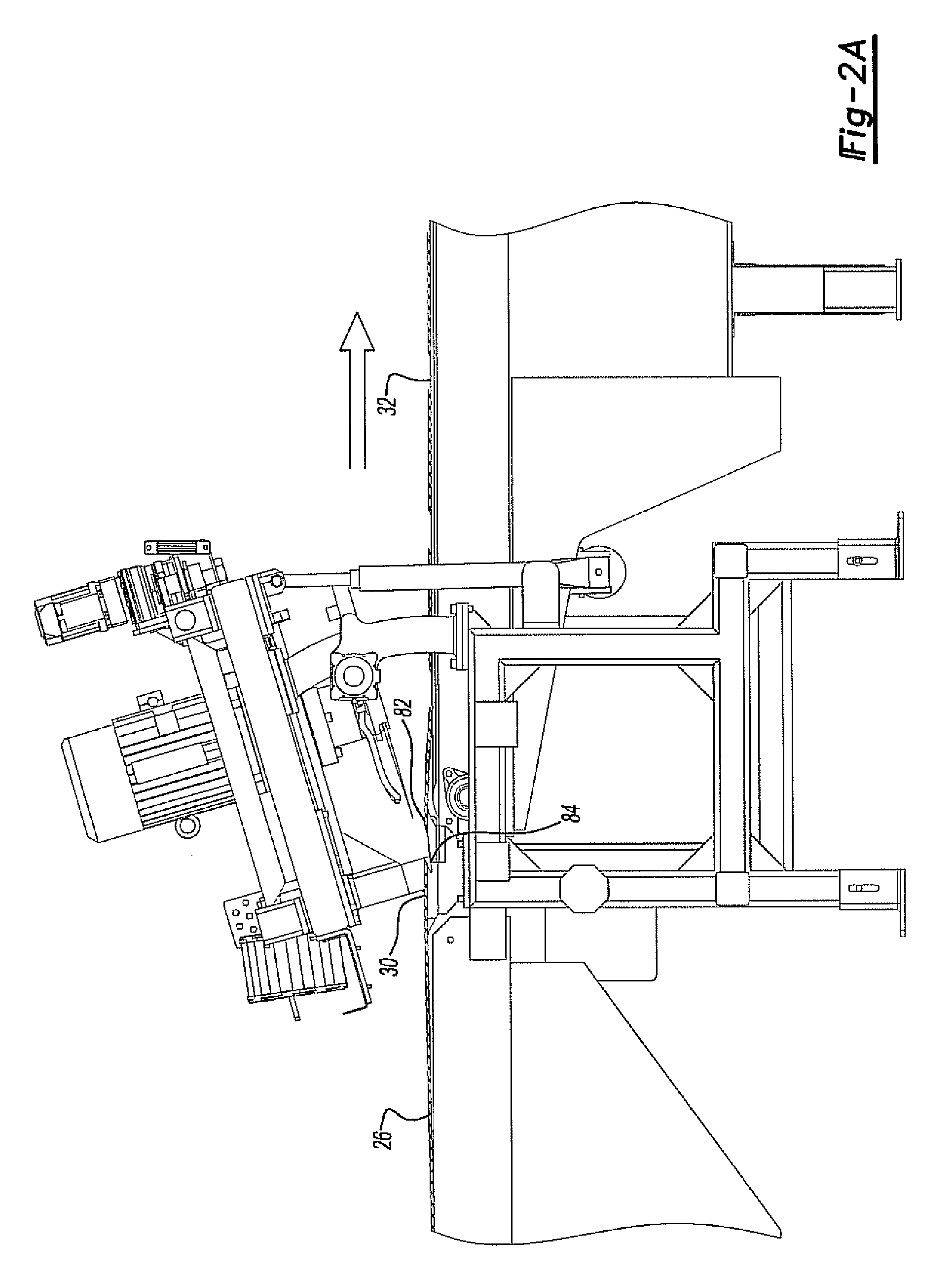
[0027]The machine 20 includes an elongated frame 24, preferably made of stainless steel, which is supported on a ground support surface. An infeed conveyor 26 extends from one end 28 of the frame 24 to a cutting platen 30. Similarly, an outfeed conveyor 32 is also mounted to the frame 24. The outfeed conveyor 32 extends from the cutting platen 30 to an outfeed end 34 of the frame 24.

[0028]Both the infeed conveyor 26 as well as the outfeed conveyor 32 are preferably belt conveyors. A first motor 36 drives the infeed conveyor 26 while a second motor 38 drives the outfeed conveyor 32, and both motors are able to have independent adjustable feed rates.

[0029]Both motors 36 and 38 are precision motors, suc...


PUM

PropertyMeasurementUnit
degree angleaaaaaaaaaa
angleaaaaaaaaaa
rotationaaaaaaaaaa

Abstract

A tire tread skiving machine having an elongated frame with two spaced ends. An elongated cutting platen extends transversely across the frame between the two ends. An infeed conveyor conveys extrusions to the cutting platen while an outfeed conveyor conveys extrusions away from the platen. A rail assembly is mounted to the frame above the cutting platen and a carriage is movably mounted to the rail assembly. A rotatably driven skiving blade is mounted to the carriage and cuts the extrusion at the cutting platen as the carriage moves along the rail assembly. The rail assembly is pivotally mounted to the frame so that the dynamically variable angle of the cut made by the skiving blade may be varied.

Description

BACKGROUND OF THE INVENTION[0001]I. Field of the Invention[0002]The present invention relates generally to a tire tread skiving machine or rubber industry.[0003]II. Description of Related Art[0004]In the production of tires for automotive vehicles, a synthetic rubber extrusion is conveyed by a conveyor to a cutting platen. At the cutting platen, a skiving blade performs the cut through the extrusion to form a length of the extrusion corresponding exactly to the required length of tire tread which can be adjusted on the fly for the particular automotive vehicles. Different tire sizes, of course, require different lengths, widths and thickness of tire tread.[0005]Each end of the tire tread extrusion is cut to a precision angle. Consequently, when the tire tread is wrapped around the carcass for the tire the two ends of the extrusion ideally meet in a flush fashion to complete the tread. The overall tire is then vulcanized to complete the manufacture of the tire.[0006]One difficulty of...

Claims


Application Information

Patent Timeline
Patent Type & Authority Patents(United States)
IPC IPC(8): B26D5/20
CPCB26D1/18B26D3/003B26D3/02B29D30/52B26D5/02B26D7/01Y10T83/444Y10T83/6569Y10T83/6582Y10T83/293Y10T83/496Y10T83/647
Inventor BRAZIER, PAUL
Owner BRAZIER PAUL
Features
  • R&D
  • Intellectual Property
  • Life Sciences
  • Materials
  • Tech Scout
  • Unparalleled Data Quality
  • Higher Quality Content
  • 60% Fewer Hallucinations
Learn More