
Gas column structure for shockproof sleeve

a technology of gas column and shock-absorbing sleeve, which is applied in the field of shock-absorbing sleeves, can solve the problems of small air bubbles that only have limited shock-absorbing capacity, the screen is likely to be damaged, and the whole electronic product becomes unusable, so as to prevent the weight from focusing and improve the strength

Active Publication Date: 2012-08-28
LIAO YAW SHIN
View PDF8 Cites 21 Cited by
  • Summary
  • Abstract
  • Description
  • Claims
  • Application Information

AI Technical Summary

Benefits of technology

[0009]A first objective of the present invention is to provide a gas column structure for a shockproof sleeve, which holds an articles in an accommodating space firmly, so as to prevent the article from shaking and rocking to have its sharp corners or hardware joints piercing a gas-column sheet and recessed buffer walls of the shockproof sleeve and cause air filled to leak out and fail. The gas-column sheet and the two recessed buffer walls form a semi-open accommodating space, and the recessed buffer walls located at two sides of the gas-column sheet can be everted upon folding lines by an external force. After an article is placed in the opened accommodating space and the external force is removed, the recessed buffer walls returns automatically, so as to hold the article in the accommodating space firmly. Thereby, the article during transportation is retained from shaking or rocking to pierce the gas-column sheet and the recessed buffer walls.
[0010]A second objective of the present invention is to provide the gas column structure for the shockproof sleeve, wherein the gas column structure has improved strength so as to better protect the article in the accommodating space from overturning and ensure sharp points of the article not to contact gas columns of the gas-column sheet and the two recessed buffer walls directly. The reason is that when the article is placed into the accommodating space of the gas column structure for the shockproof sleeve, the gas-column sheet serves to carry the article and allow the article to lie levelly on the gas-column sheet, so the gas columns of the gas-column sheet and the two recessed buffer walls can evenly share the weight of the article, so as to prevent the weight from focusing on one point and breaking the gas column.
[0011]A third objective of the present invention is to provide the gas column structure for the shockproof sleeve, wherein corners of the gas column structure for the shockproof sleeve are secured from being damaged an losing their buffing function. The middle short gas columns of the U-shaped members at two sides of the recessed buffer walls are unfilled, so that four corners of the gas column structure for the shockproof sleeve are free from being broken when contacting sharp points, thereby ensuring buffing effects of the corners of the shockproof sleeve.
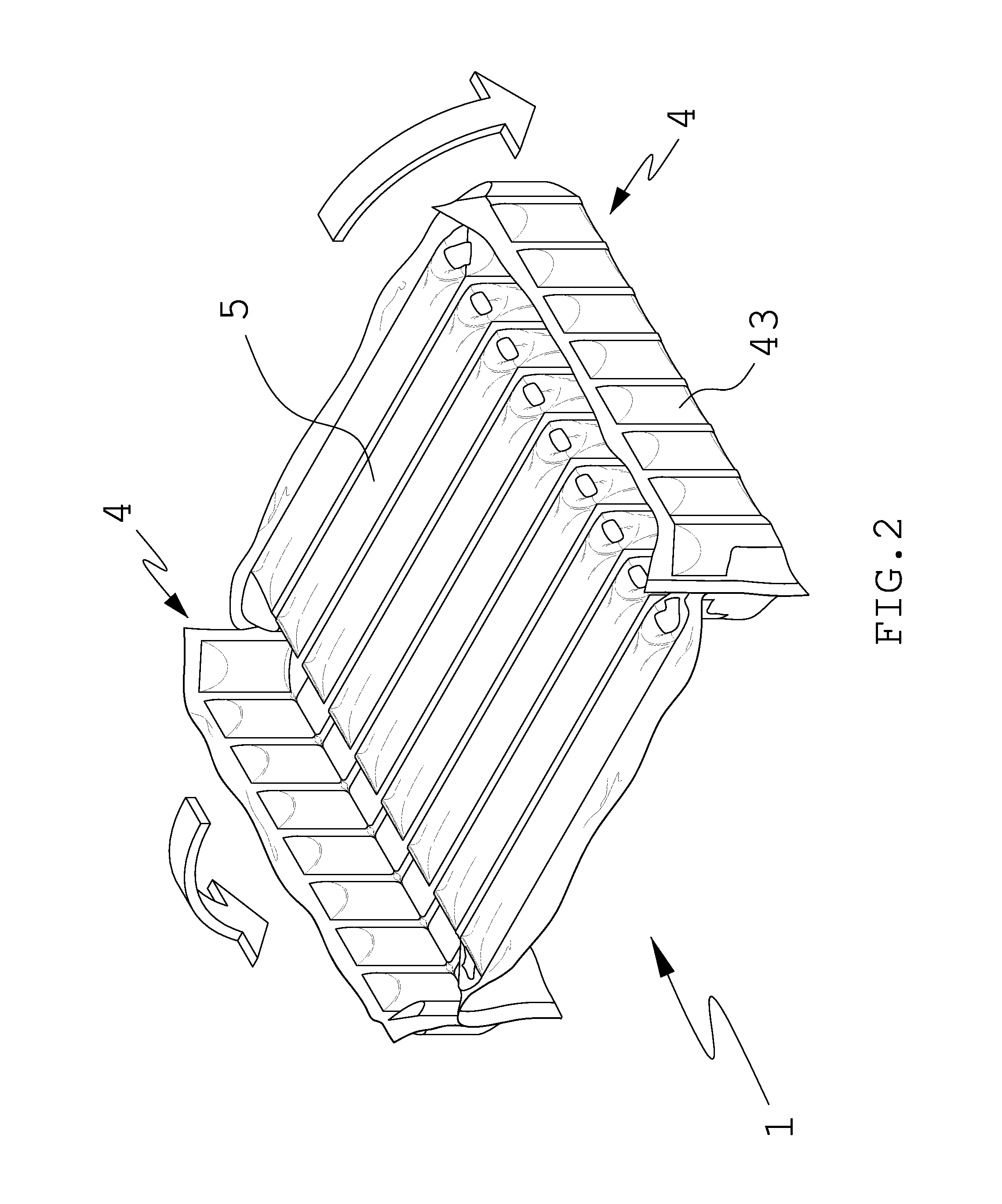
[0012]A fourth objective of the present invention is to provide the gas column structure for the shockproof sleeve, wherein each of the U-shaped members of each of the two recessed buffer walls has a terminal formed as a node, and after plural said U-shaped members are connected abreast through heat sealing into one said recessed buffer wall, the nodes form a second folding line and an additional gas-column sheet is connected to each of the second folding lines, the additional gas-column sheets being configured to be pulled down and positioned above the accommodating space to allow the shockproof sleeve to provide double protection.
[0013]A fifth objective of the present invention is to provide the gas column structure for the shockproof sleeve, wherein a dark screen is additionally provided for covering the accommodating space, and the dark screen maybe realized by an additional dark gas-column sheet that is attached to any of the recessed buffer walls of the gas columns by means of heat sealing, so that the dark gas-column sheet serves as a moveable screen that covers and thereby protects the semi-open accommodating space.
[0014]A sixth objective of the present invention is to provide the gas column structure for the shockproof sleeve, wherein the shockproof sleeve is especially suitable for articles with sharp ends or of irregular shape because the gas columns are gas-column sheet are formed into irregular shapes when arranged into connected, abreast said gas columns through heat sealing, so that the gas columns are less likely to be pricked by any sharp point of an article received in the shockproof sleeve and that sites where sealing lines are formed are depressed from two adjacent gas columns and ideal to receive the sharp points, thereby holding the article firmly in the accommodating space.

Problems solved by technology

In the event that these modern portable electronic products get impacted at the screens, the screens are likely to be damaged and then the whole electronic products become unusable.
However, those small air bubbles have only limited shock-absorbing capability and may fail to provide shockproof and buffing effects against heavy shock or impact.
However, in view that EVA is relatively costly, air-filled packaging bags have been developed as a new packaging and buffing material.
However, when an article is received in the accommodating space, the article is not tightly close to the buffer portions and tends to shake and rock in the accommodating space, so the sleeve can get pierced by sharp corners or hardware joints of the article.
Once the sleeve is broken, air filled therein will leak out and the article losing protection may be impacted or scraped.
Although there are two buffer walls, namely the first buffer wall and the second buffer wall, the accommodating space is not flat-bottomed, so when the article is placed at the edges near where the nodes are formed, the article having its weight pressing on the gas columns may pierce the gas columns to cause air leakage.
As a result, the air shockproof sleeve will lose its protective function.
While the prior-art gas-filled packing bag with multiple auxiliary gas columns is capable of bearing heavy impact, it is not suitable for packing articles with sharp points and it fails to propose a solution for the folds at the corners of the bag caused by bent gas columns.

Method used


Image

  • Gas column structure for shockproof sleeve
  • Gas column structure for shockproof sleeve
  • Gas column structure for shockproof sleeve

Examples


Embodiment Construction

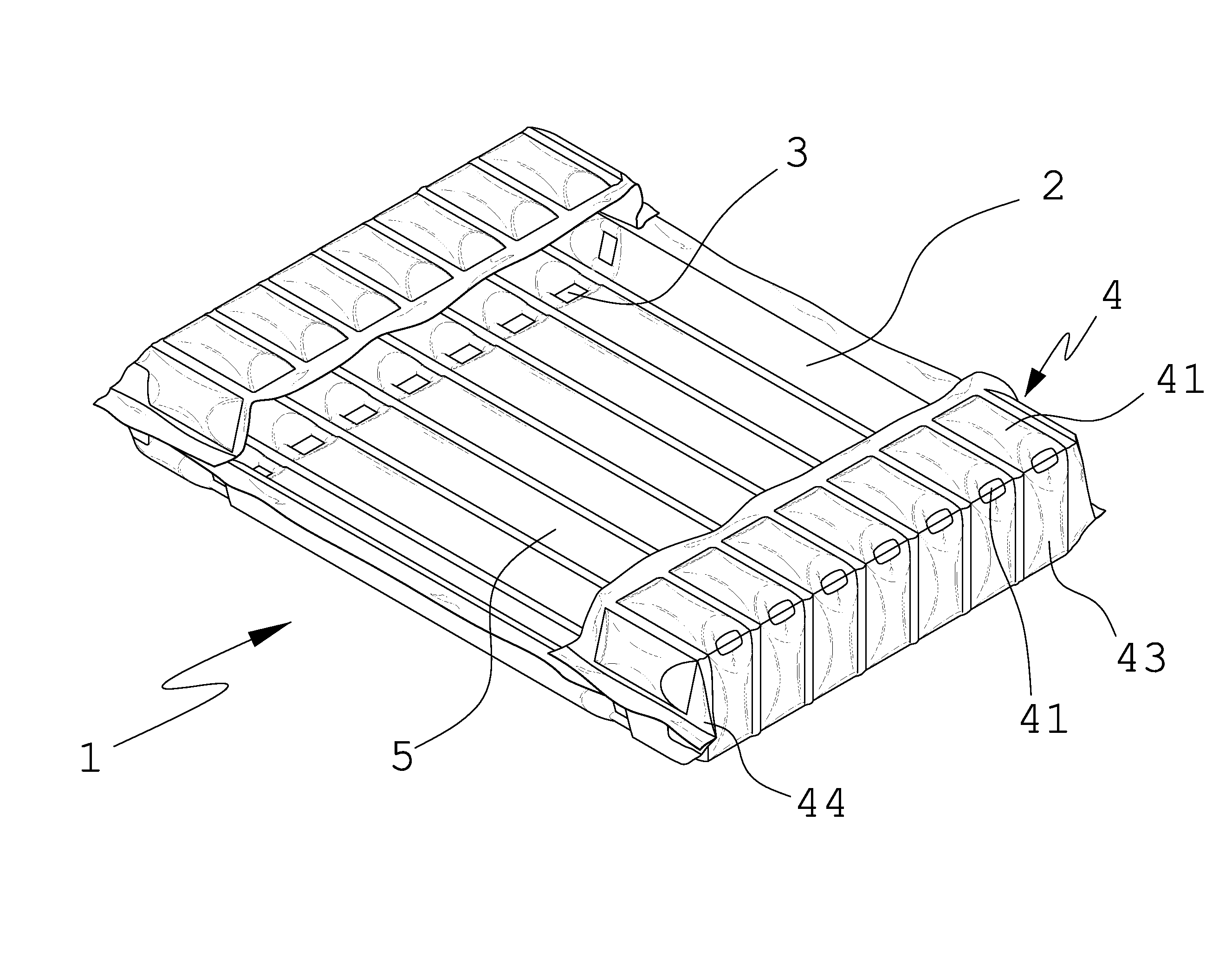
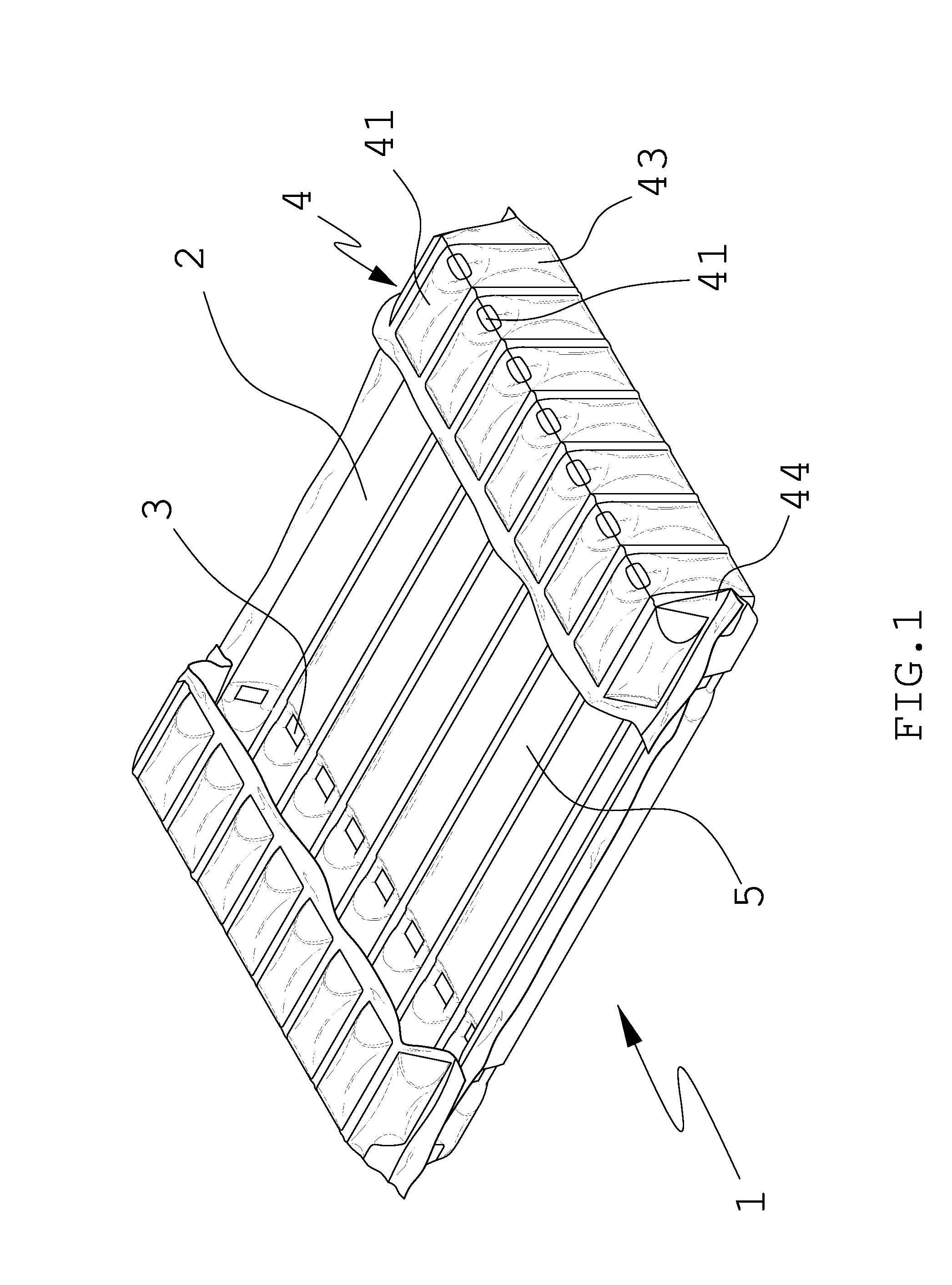
[0023]First, please refer to FIG. 1, FIG. 2, FIG. 3, FIG. 4 and FIG. 5, for a perspective view of the present invention according to a first embodiment, a first applied view of the first embodiment, a second applied view of the first embodiment, a perspective view of the present invention according to a second embodiment, and an applied view of the second embodiment. As shown clearly in the drawings, a gas column structure for a shockproof sleeve 1 is composed of a gas-column sheet 2, two folding lines 3 and two recessed buffer walls 4.

[0024]The gas-column sheet 2 includes a plurality of gas columns formed and arranged abreast through heat sealing for receiving an article to be protected.

[0025]Each of the two folding lines 3 is composed of a plurality of folding nodes. The number of the folding nodes is equal to the number of the gas columns of the gas-column sheet 2 and the number of adjacent U-shaped members 43. The folding lines 3 are such connected to two ends of the gas-column ...


PUM


Abstract

A gas column structure for a shockproof sleeve includes a gas-column sheet, two folding lines and two recessed buffer walls. Each of the recessed buffer walls has U-shaped members formed abreast through heat sealing. The middle short gas columns of the U-shaped members at two sides of the recessed buffer walls are unfilled, so that four corners of the gas column structure for the shockproof sleeve are free from being broken when contacting sharp points. The gas columns of the gas-column sheet may be formed through heat sealing to have irregular shapes, so the gas-column sheet is ideal for articles with sharp points and / or irregular shapes. A dark screen may be additionally provided for covering the accommodating space as a movable screen that covers and thereby protects the semi-open accommodating space.

Description

BACKGROUND OF THE INVENTION[0001]1. Technical Field[0002]The present invention relates to shockproof sleeves for electronic products, and more particularly, to a gas column structure for a shockproof sleeve.[0003]2. Description of Related Art[0004]Shockproof sleeves are extensively used to wrap and protect electronic products, such as projectors, DVD, digital cameras, laptop computers and mobile phones. The electronic products in early times were rarely provided with display screens and even those with screens had relatively small screens. However, the trend for modern portable electronic products, such as mobile phones and game players, is that the screens equipped are increasingly enlarged. In the event that these modern portable electronic products get impacted at the screens, the screens are likely to be damaged and then the whole electronic products become unusable. Thus, shockproof sleeves have been developed with increasingly launched portable electronic products, such as tho...

Claims


Application Information

Patent Timeline
IPC IPC(8): B65D81/02
CPCB65D81/03B65D81/052
Inventor LIAO, YAW SHIN
Owner LIAO YAW SHIN
Learn More