
Modular initiator

a modular initiator and initiator technology, applied in the direction of manufacturing tools, electric fuzes, borehole/well accessories, etc., can solve the problems of additional problems, final steps can be problematic, and danger to personnel in the vicinity

Active Publication Date: 2012-09-04
BAKER HUGHES HLDG LLC
View PDF19 Cites 74 Cited by
  • Summary
  • Abstract
  • Description
  • Claims
  • Application Information

AI Technical Summary

Problems solved by technology

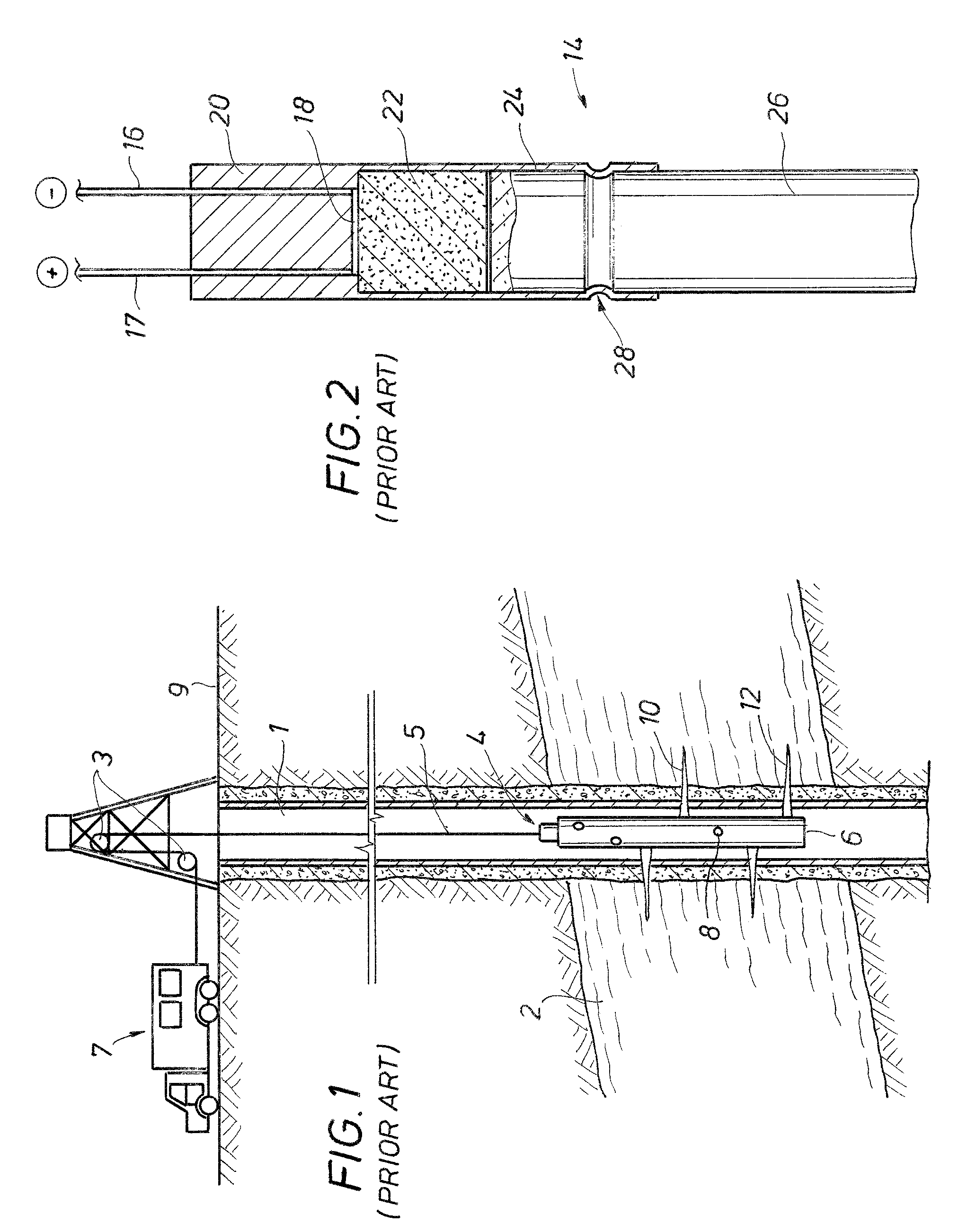
Additional problems may be encountered in the field when connecting initiators to the detonation cord.
These final steps can be problematic during inclement weather.
Additionally, these final steps fully load a perforating gun and thus pose a threat to personnel in the vicinity.

Method used


Image

  • Modular initiator
  • Modular initiator
  • Modular initiator

Examples


Embodiment Construction

[0019]The present invention will now be described more fully hereinafter with reference to the accompanying drawings in which embodiments of the invention are shown. This invention may, however, be embodied in many different forms and should not be construed as limited to the illustrated embodiments set forth herein; rather, these embodiments are provided so that this disclosure will be thorough and complete, and will fully convey the scope of the invention to those skilled in the art. Like numbers refer to like elements throughout. For the convenience in referring to the accompanying figures, directional terms are used for reference and illustration only. For example, the directional terms such as “upper”, “lower”, “above”, “below”, and the like are being used to illustrate a relational location.

[0020]It is to be understood that the invention is not limited to the exact details of construction, operation, exact materials, or embodiments shown and described, as modifications and equ...


PUM

PropertyMeasurementUnit
perforating lengthaaaaaaaaaa
rotationaaaaaaaaaa
electrical currentaaaaaaaaaa

Abstract

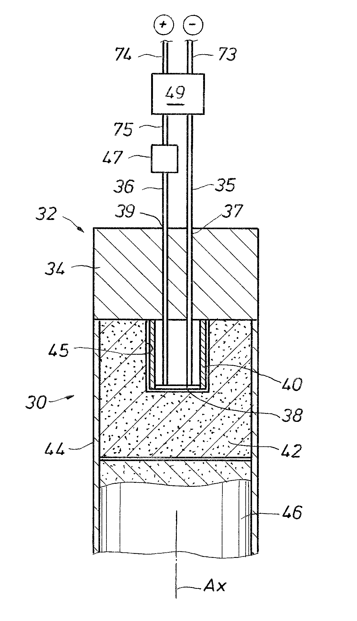
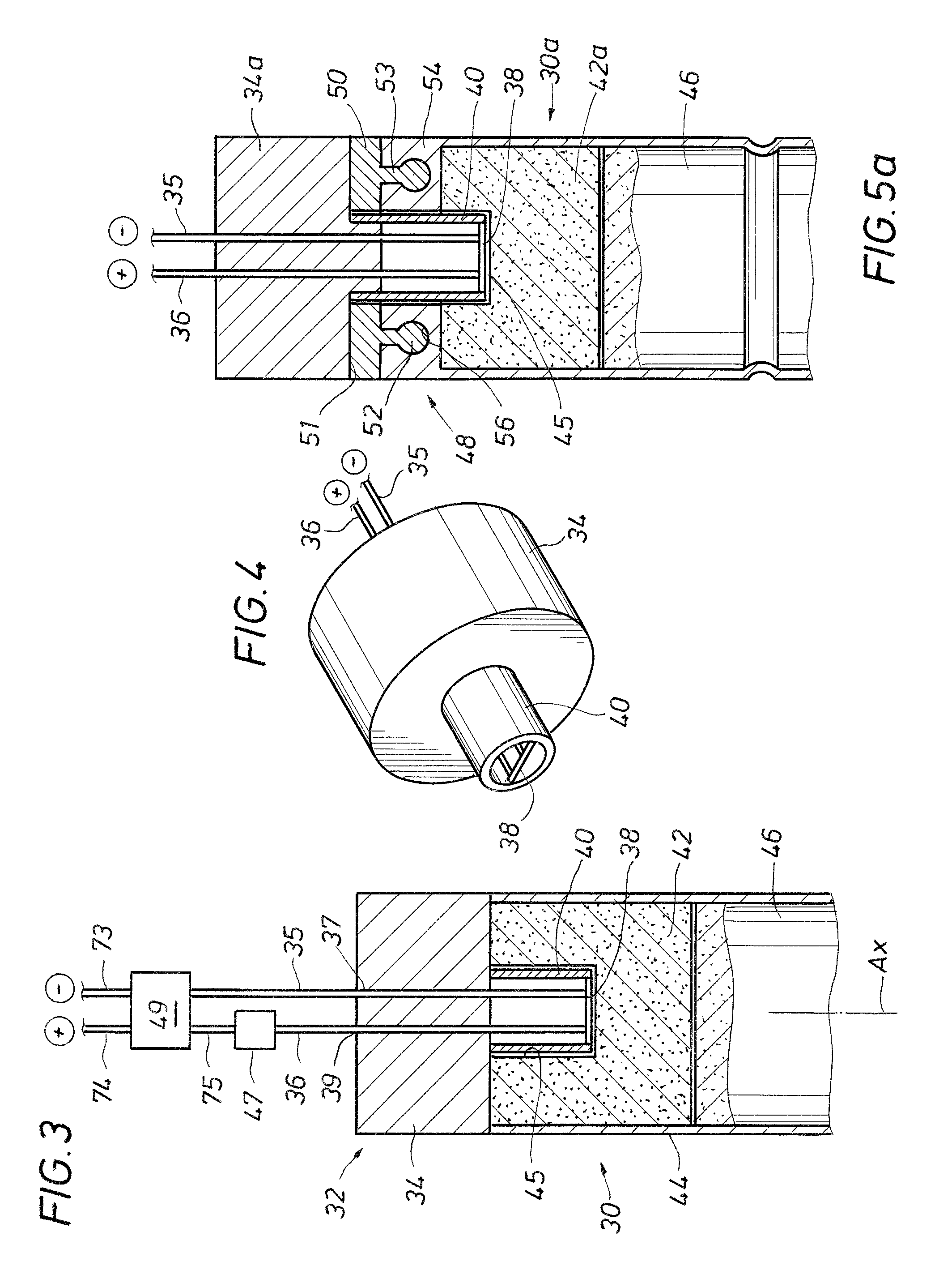
An initiator for initiating detonation in a detonation cord of a perforating system, where the initiator comprises a modular electronic igniter that quick connects into a portion of high explosive. The high explosive is disposed in a housing having an end of detonation cord crimped therein. The electronic igniter may be shipped to the field and / or stored separate from the high explosive then the two may be assembled just prior to deploying the perforating gun assembly in a wellbore. Various methods of quick connecting the electronic igniter to the high explosive may be used.

Description

BACKGROUND[0001]1. Field of Invention[0002]The invention relates generally to the field of oil and gas production. More specifically, the present invention relates to a perforating system. Yet more specifically, the present invention relates to a modular initiator for use in a perforating gun system.[0003]2. Description of Prior Art[0004]Perforating systems are used for the purpose, among others, of making hydraulic communication passages, called perforations, in wellbores drilled through earth formations so that predetermined zones of the earth formations can be hydraulically connected to the wellbore. Perforations are needed because wellbores are typically completed by coaxially inserting a pipe or casing into the wellbore. The casing is retained in the wellbore by pumping cement into the annular space between the wellbore and the casing. The cemented casing is provided in the wellbore for the specific purpose of hydraulically isolating from each other the various earth formations...

Claims


Application Information

Patent Timeline
Patent Type & Authority Patents(United States)
IPC IPC(8): E21B43/116
CPCE21B43/1185F42B3/12F42B3/121F42B3/26F42C19/12F42D1/045F42D1/055F42B3/103F42B3/198F42D1/043Y10T29/49826
Inventor HILL, FREEMAN L.EVANS, RANDY L.
Owner BAKER HUGHES HLDG LLC
Learn More