
Apparatus and method for severing pipe utilizing a multi-point initiation explosive device

a multi-point initiation and explosive device technology, applied in the direction of nuclear explosives, borehole/well accessories, nuclear engineering, etc., can solve the problems of large hydrostatic pressure, insufficient pressure increase to achieve the desired severance, and the sidewall of the wellbore may be damaged, so as to enhance the separation effect of multiple pressure waves and the subsequent wave collision

Active Publication Date: 2006-09-12
HALLIBURTON ENERGY SERVICES INC
View PDF11 Cites 57 Cited by
  • Summary
  • Abstract
  • Description
  • Claims
  • Application Information

AI Technical Summary

Benefits of technology

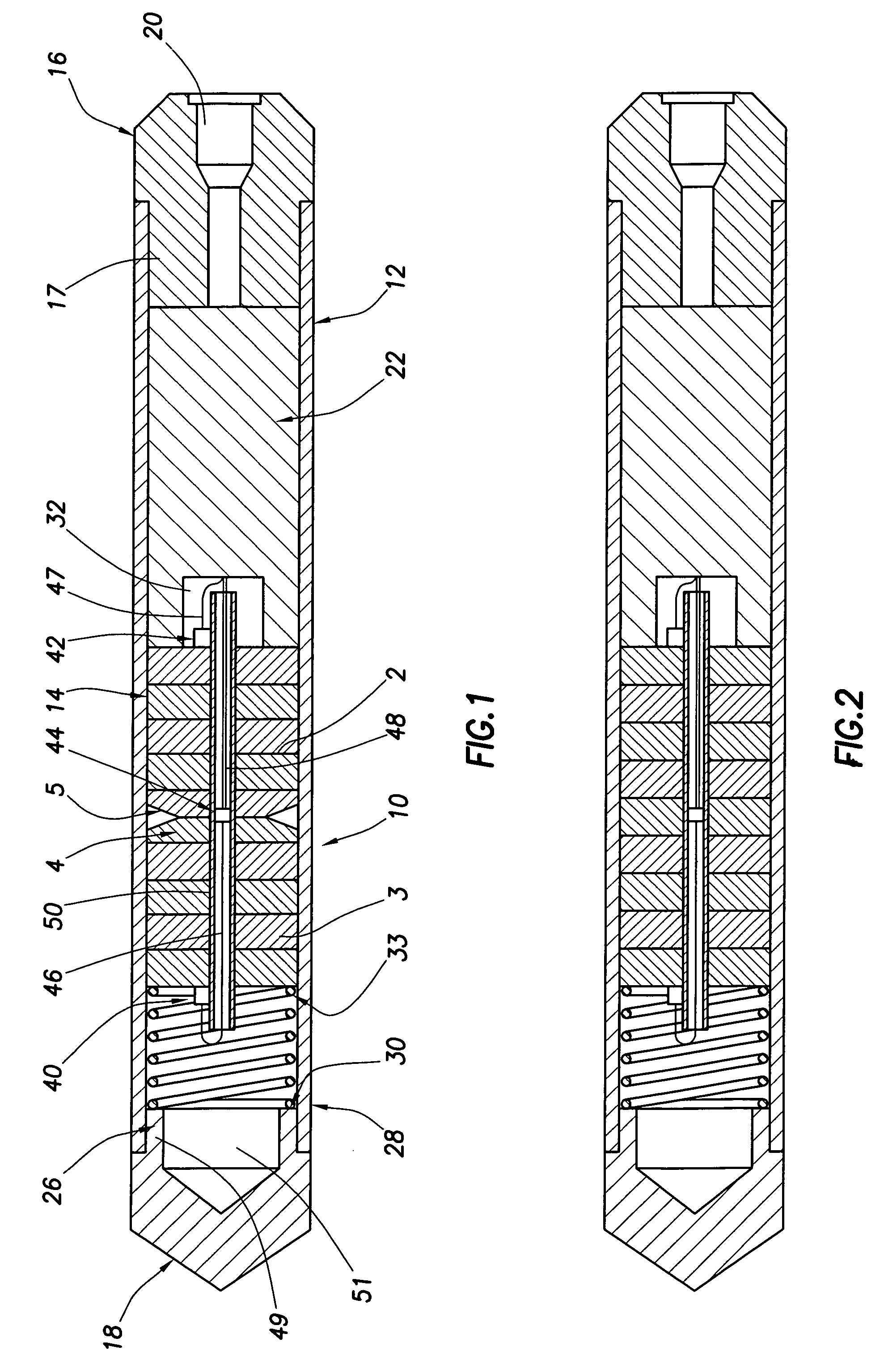
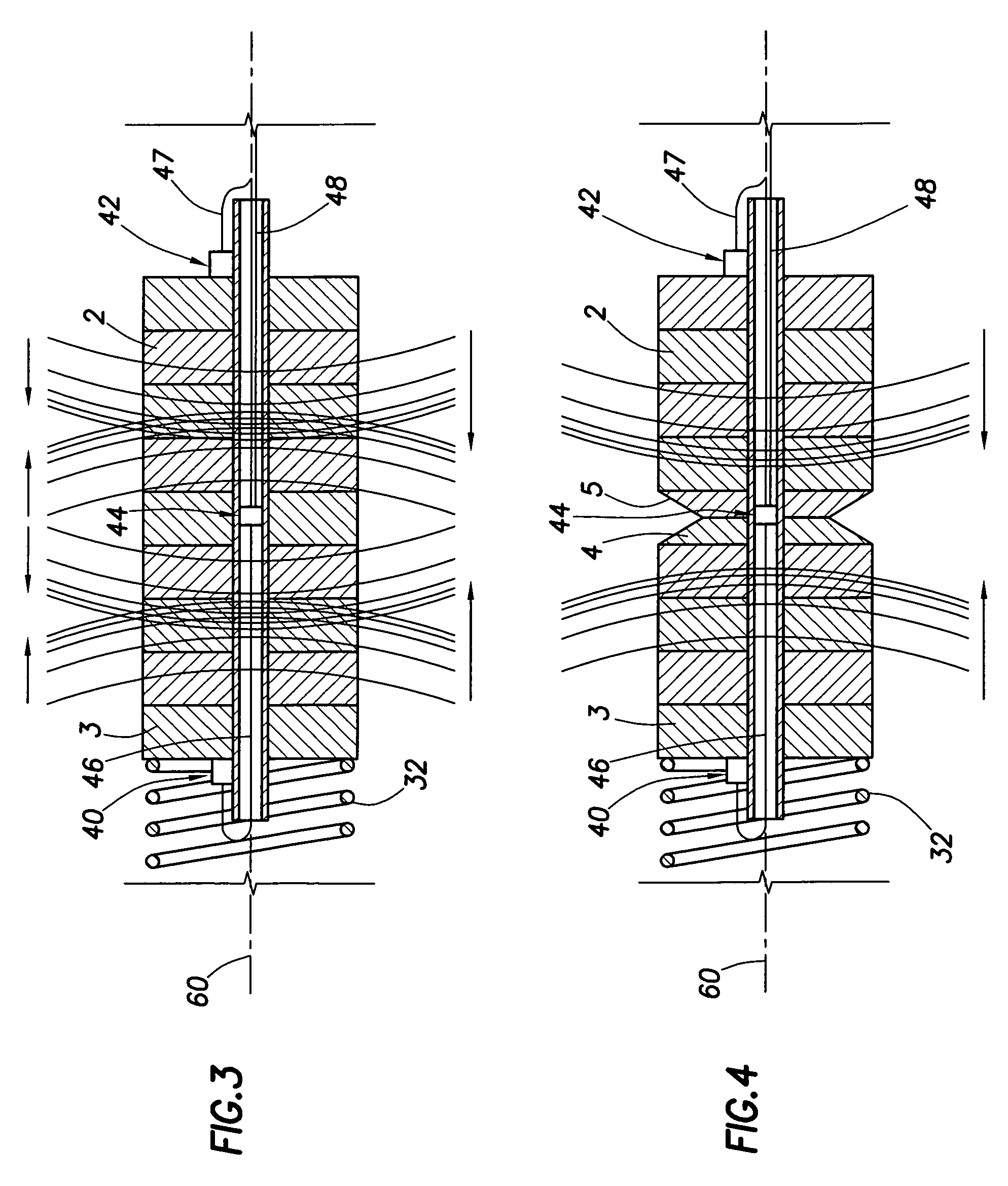
The present patent describes a multi-point initiation explosive severing device and a method for severing a tubular structure using the device. The device includes an interior housing with an explosive collection located inside. The device has three initiators located at different locations in the housing. A detonator can be used to initiate a timed sequence of the initiators. The device also includes a shaped charge and liner that causes pre-scoring of the pipe or tubing at the point of intended separation, enhancing the separation effect of the multiple pressure waves and the subsequent wave collisions. The method involves locating an explosive collection in the tubular structure with at least two pressure waves created by using the initiators. Another pressure wave is created in between the first and second pressure waves. The device and method can be used for impacting a structure by creating at least two pressure waves with at least one wave originating in each region of the explosive collection.

Problems solved by technology

For example, the wellbore sidewall may collapse against the drill string preventing it from being moved within or removed from the well bore.
The depth at which such operations may occur may result in large hydrostatic pressure that tends to attenuate and suppress the pressure of the explosive pulse and prevent severance of the tubing.
Notwithstanding the increase of the intended pipe severing pressure pulse generated by the colliding wave fronts, the increase of pressure may be insufficient to effect the desired severance of tubing at certain depths and for certain thicknesses of pipe, tubing or casing.

Method used


Image

  • Apparatus and method for severing pipe utilizing a multi-point initiation explosive device
  • Apparatus and method for severing pipe utilizing a multi-point initiation explosive device
  • Apparatus and method for severing pipe utilizing a multi-point initiation explosive device

Examples


Embodiment Construction

[0032]The present disclosure relates to an explosive severing device and a method for producing an enhanced pressure wave phenomenon. The device is used typically for severing thick wall tubular targets by detonating an explosive charge within the annulus of a target pipe where conventional cutting devices are limited in effect or ineffective due to extreme thickness of the target pipe or due to extreme hydrostatic pressures attenuating the effect of the explosion, such as in a deep oil or gas well. The device and method are not limited to these types of targets and may also be used for thin wall targets and less extreme hydrostatic pressures.

[0033]The device and method of the present disclosure typically use an explosive material or collection of explosive materials to create multiple pressure waves. An explosive material is a material that, under defined conditions, will explode creating a pressure wave. An explosive material maybe made up of multiple components, which include mul...


PUM


Abstract

A system and method for making and using a multi-point initiation explosive device that produces an enhanced pressure wave for severing tubing, pipe or casing in an oil or gas well. At least two opposed initiators initiate a column of explosive material from opposite ends, thereby generating opposing pressure waves propagating toward a midpoint between the initial initiators. A shaped-charge assembly with a liner located at the midpoint initiates immediately prior to the arrival of the opposing pressure waves and forms a fast moving jet to pre-score the target pipe prior to the arrival of the pressure pulse propagating from the initial detonations.

Description

CROSS-REFERENCE TO RELATED APPLICATIONS[0001]None.STATEMENT REGARDING FEDERALLY SPONSORED RESEARCH OR DEVELOPMENT[0002]Not applicable.REFERENCE TO A MICROFICHE APPENDIX[0003]Not applicable.FIELD OF THE INVENTION[0004]The present invention is concerned with method for making and using a multi-point initiation explosive device that produces an enhanced pressure wave and more particularly to a system and for severing tubing, pipe or casing or otherwise impacting downhole structures in an oil or gas well using a multi-point initiation explosive device.BACKGROUND OF THE INVENTION[0005]The use of explosive devices for severing tubing, pipes, or casings used to line wells such as oil and natural gas wells and the like, is well-known in the art. For example, U.S. Pat. Application Publication No. U.S. 2003 / 0047312, published Mar. 13, 2003, by William T. Bell, discloses a method and device for severing drill-pipe, casing and other massive tubular structures by the remote detonation of an expl...

Claims


Application Information

Patent Timeline
Patent Type & Authority Patents(United States)
IPC IPC(8): E21B29/02E21B43/11
CPCE21B29/02F42B1/00
Inventor GRATTAN, ANTONY F.PATTERSON, MICHAEL L.BARKER, JAMES M.WUENSCHE, THOMAS J.
Owner HALLIBURTON ENERGY SERVICES INC
Learn More