Self-adaption compression ratio variable engine

An engine, self-adaptive technology, applied in engine components, engine control, combustion engine, etc., can solve problems such as low efficiency, small compression ratio, high compression ratio, etc.

Inactive Publication Date: 2008-01-23
陈晨
View PDF0 Cites 57 Cited by
  • Summary
  • Abstract
  • Description
  • Claims
  • Application Information

AI Technical Summary

Problems solved by technology

[0003] 2. Limited by the vibration phenomenon, too high compression ratio cannot be used
[0005] 4. For engines with fixed compression ratio, the compression ratio can only be determined according to the maximum throttle opening, resulting in too small compression ratio, incomplete combustion, low efficiency and low power in the state of small throttle
[0007] 6. At present, automobile engines work in a small throttle state for a large amount of time, that is, automobiles with fixed compression ratio engines, in most cases, the combustion is incomplete, the efficiency is low, and the power is small
[0009] 8. Although there are various design samples and patents of variable compression ratio engines at present, the mechanical structure and electronic control are too complicated and difficult to manufacture, and none of them have entered practical mass production
[0010] To sum up, for an engine with a fixed compression ratio, the determination of the compression ratio is limited by the shock vibration caused by the maximum throttle opening, which is often low, and the car is in a small throttle state most of the time, especially in urban areas and idling states In this state, the engine whose compression ratio is determined according to the maximum throttle opening deviates far from the ideal compression ratio, resulting in incomplete combustion, low efficiency and low power

Method used


Image

  • Self-adaption compression ratio variable engine
  • Self-adaption compression ratio variable engine
  • Self-adaption compression ratio variable engine

Examples


Embodiment Construction

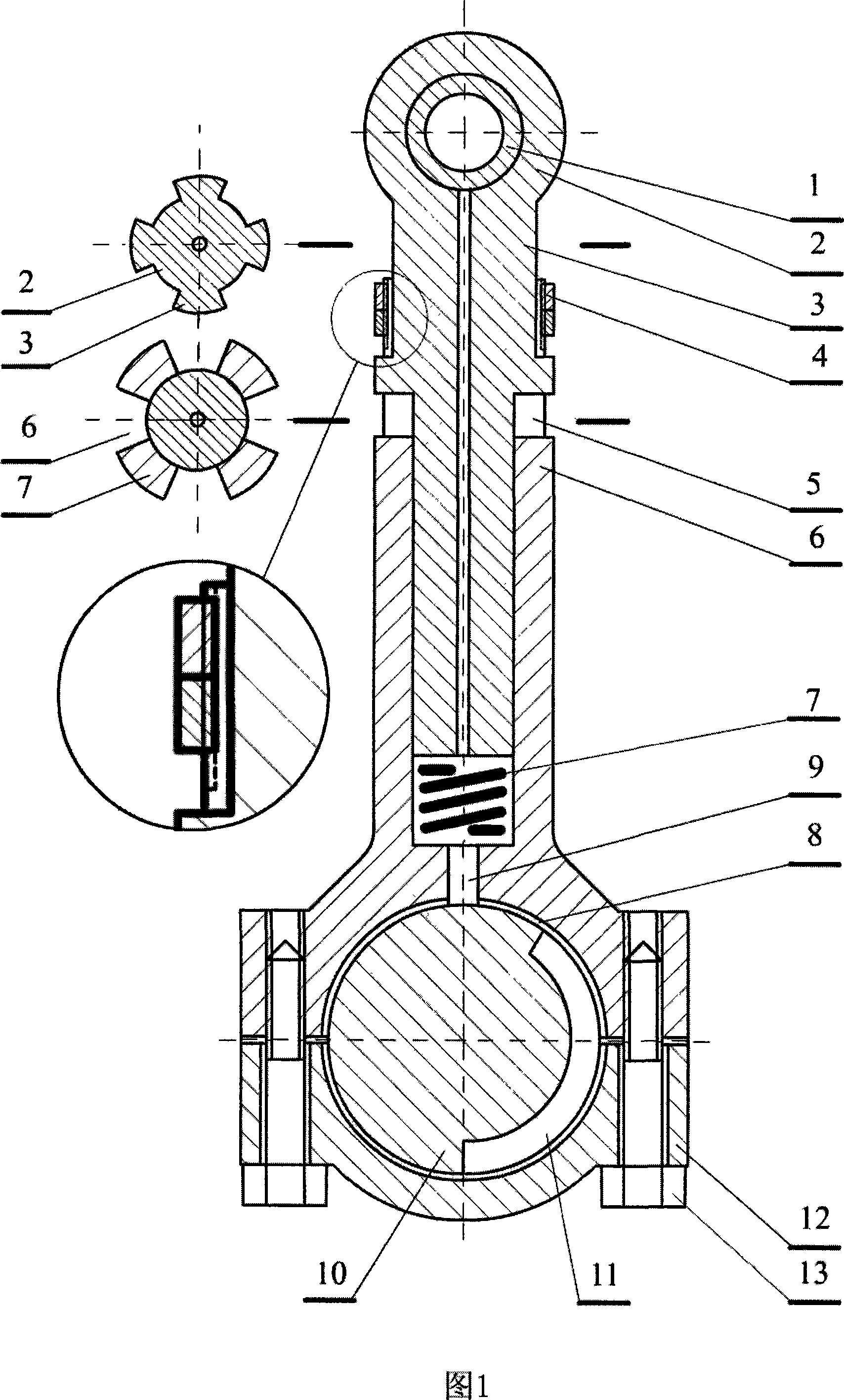
[0045] 1. Draw a picture according to Figure 1 and process the parts of the plunger connecting rod.

[0046] 2. Assemble the connecting rod according to Figure 1, put in the spring 7 first, insert the plunger 2, and then install the circlip or nut 4.

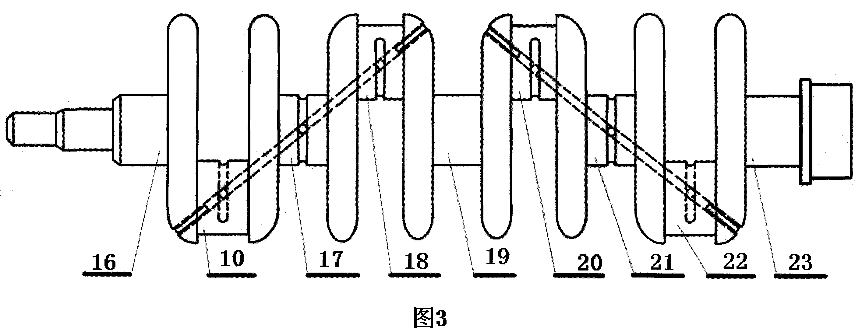
[0047] 3, the crankshaft increases the oil passage, as shown in Figure 3 and 4, the oil passage 25 is obtained by drilling, the two bearing neck annular oil grooves 27 of the lathe machining crankshaft, the four connecting rod neck oil supply grooves 11 of the milling machine processing crankshaft, and drilling Obtain the communication hole 26 from the oil passage 25 to the oil groove 11, drill a hole to obtain the communication hole 28 from the oil passage 25 to the oil groove 27, clean the oil passage and seal the process hole 24.

[0048] 4. Drill the upper half of the sliding bearing.

[0049] 5. Process the cylinder block oil circuit according to Figure 5. Drill the horizontal main oil passage, vertical branch oil passage...


PUM


Abstract

An engine with variable compression ratios that is simple, reliable and cheap is provided. The compression ratio is at maximum at idling, and is at minimum at the max. valve position, and can be changed automatically and continuously under any valve position, so that the compression ratio of the engine will approach to the max. allowable value for detonation, so the engine is of very high efficiency and substantially complete combustion, very low emission of waste gas, and is a target pursued by the automobile industry at present in the world. The principle of the invention is, a link rod of variable lengths is used, and the length of the link rod is depending upon the pressure of the combustible mixture gas before ignition combustion; when the pressure is approaching and exceeding the detonation pressure, the link rod will shorten automatically, the compression ratio will drop, so that the pressure will not increase any more, and detonation is avoided. The key tech in the invention is that the link rod uses a plunger type hydraulic cylinder, the oil in which is supplied and closed by the neck connected by the link rod on the crankshaft, so that the length of the link rod is variable in the compression period, and not variable during the ignition and work period.

Description

Technical field [0001] The invention relates to a new engine device capable of automatically adjusting the compression ratio, in particular, it can automatically adjust the compression ratio under different throttle opening conditions, so that the compression ratio approaches the maximum permissible value of critical detonation, and realizes the purpose of high-efficiency combustion and low emission , is an environmentally friendly and energy-saving engine. Background technique [0002] 1. High compression ratio is conducive to full combustion and improved engine power. In the engine combustion chamber, the higher the pressure of the mixed gas, the easier it is to burn, the higher the efficiency and the lower the emission, which is the pursuit of engine manufacturing. [0003] 2. Limited by the vibration phenomenon, too high compression ratio cannot be used. When the compression ratio is too high, spontaneous combustion will occur, which will cause violent vibration, serio...

Claims


Application Information

Patent Timeline
Patent Type & Authority Applications(China)
IPC IPC(8): F02B75/04F02D15/02F16C7/06
CPCF02B41/04F02B75/045F16C7/04F16C7/06F16C2360/22Y02T10/12
Inventor 陈晨
Owner 陈晨
Why Eureka
Try Eureka