Vehicle suspension spring system

a suspension spring and vehicle technology, applied in the direction of vehicle springs, resilient suspensions, vibration dampers, etc., can solve the problems of reducing the handling characteristics of both types of suspension configuration, and reducing the ride quality of the vehicle, so as to reduce the lateral displacement of the centre of gravity, and reduce the jacking effect

Inactive Publication Date: 2010-08-24
TECH INVESTMENTS
View PDF6 Cites 77 Cited by
  • Summary
  • Abstract
  • Description
  • Claims
  • Application Information

AI Technical Summary

Benefits of technology

[0012]The present invention provides a vehicle suspension spring system which manipulates the spring rate of each individual hydro-pneumatic suspension spring system on a vehicle without the need for cross-linking and / or external oil reservoirs and the associated pumps.
[0052]Gentle lateral accelerations require only the switching of the unloaded wheel stations to the high rate to eliminate the jacking effect of these wheels travelling quickly into rebound. For more extreme manoeuvres such as double lane change emergency avoidance manoeuvres, the control system can immediately switch all wheel stations to the higher spring rate, minimising lateral displacement of the centre of gravity and thus minimising roll and providing maximum stability and handling performance.
[0053]Emergency braking manoeuvres are usually accompanied by severe pitching of the vehicle with the front end diving and the rear rising up leading to a loss of traction. The proposed system offers a means of controlling this by allowing the spring rates to be increased for the duration of the braking event.

Problems solved by technology

While a stiffer suspension is essential to enhance the rollover threshold value and control performance of the vehicle, a softer suspension yields good ride performance at the expense of poor stability and directional control.
Both wheels respond as one unit, which detracts from the ride quality of the vehicle.
However, the handling characteristics of both types of suspension configuration suffer when soft springs are used because of excessive roll.
The same however is not true for independent suspension systems.
This, while increasing the roll stability of the vehicle, produces a significant loss in ride quality, especially in challenging environments.
Such systems again serve to detract from the independence of an independent suspension system, compromising on ride quality.

Method used


Image

  • Vehicle suspension spring system
  • Vehicle suspension spring system
  • Vehicle suspension spring system

Examples


Embodiment Construction

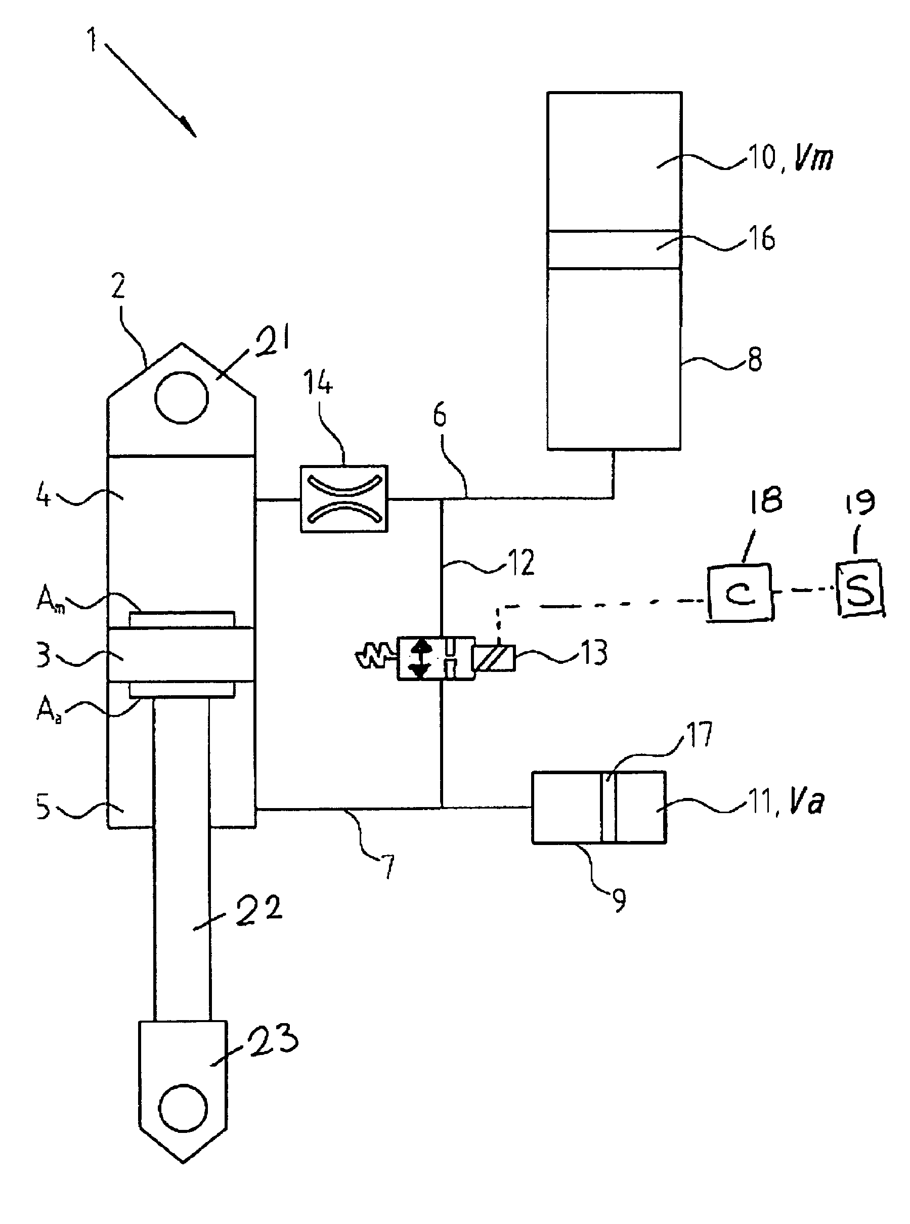
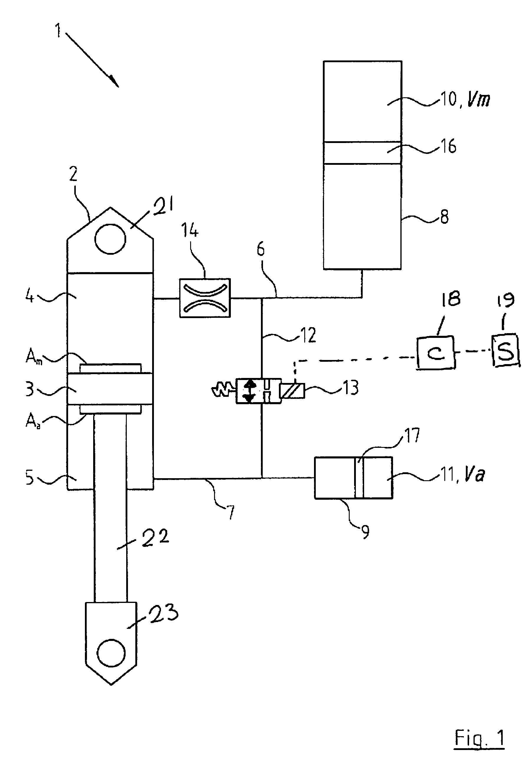
[0059]The system, for the purposes of clarity, is represented diagrammatically in FIG. 1 as individual hydraulic components. It can be constructed as shown, but the preferred layout is one of an integrated strut utilizing internal volumes and valves, as opposed to externally linked components.

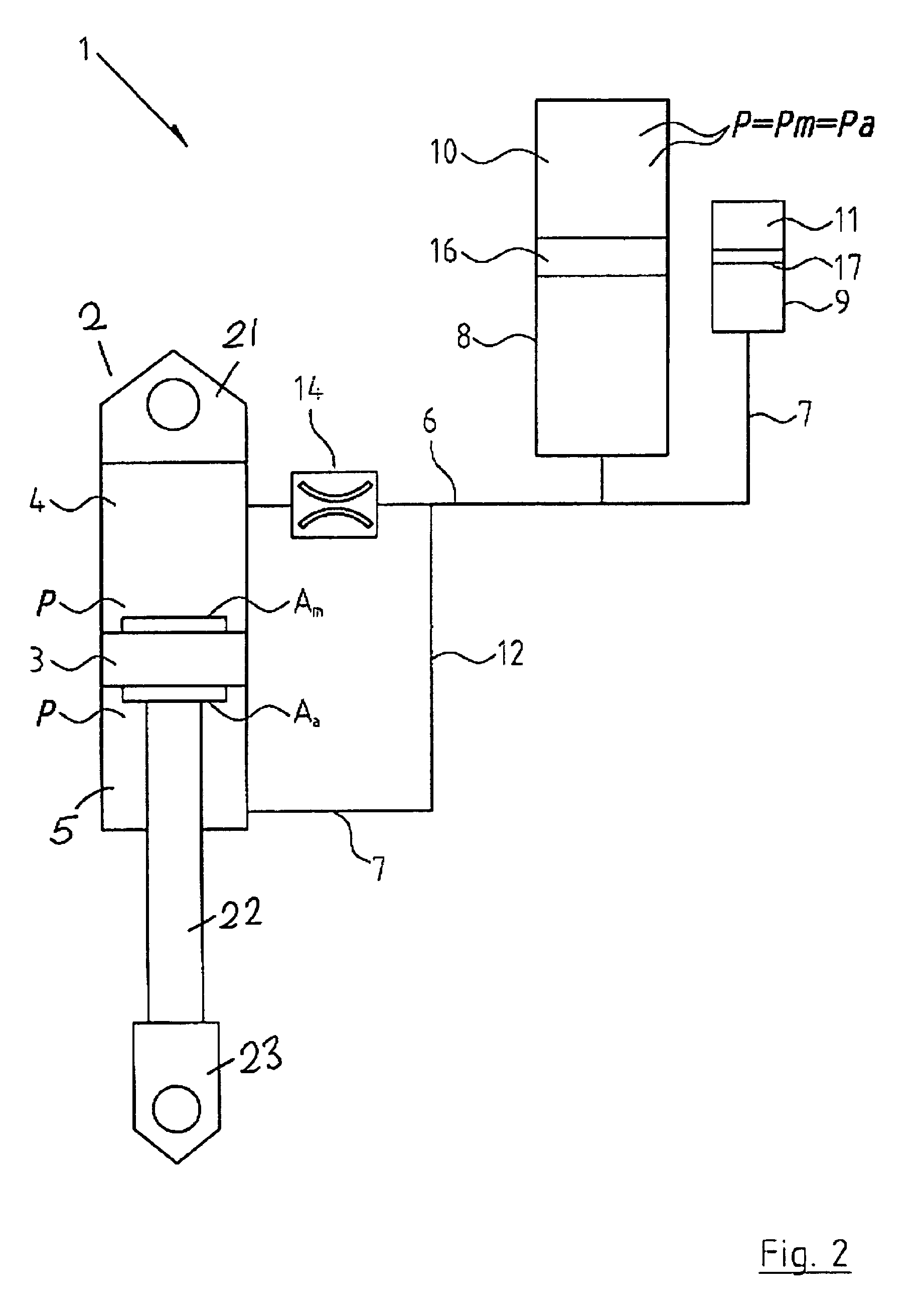
[0060]Referring to the drawings, there is illustrated a vehicle suspension spring system according to the invention indicated generally by the reference numeral 1. The suspension spring system 1 includes an hydraulic cylinder or strut 2 with piston 3 which has different areas Am and Aa on each side. The piston 3 separates the hydraulic cylinder 2 into two volumes, the main oil volume 4 and the annular oil volume 5. Each volume 4 and 5 is connected hydraulically via oil lines or first and second oil passages 6 and 7 to accumulators 8 and 9 such that the oil pressures in volumes 4 and 5 act on a main gas volume 10 and an auxiliary gas volume 11 respectively. The oil in each accumulator 8, 9 is se...


PUM


Abstract

A vehicle suspension spring system for a vehicle wheel station includes a hydraulic cylinder or strut having a piston which divides the cylinder volume into a main oil volume and an annular oil volume. The main oil volume communicates via a first oil passage with a first accumulator having a main gas volume. The annular oil volume communicates via a second oil passage with a second accumulator having an auxiliary gas volume. The oil in each accumulator is separated from the gas by a separator piston or diaphragm. A third oil passage with an isolating valve interconnects said first and second oil passages. Operation of the isolating valve is regulated by a controller. At least one sensor for sensing a parameter associated with vehicle attitude is connected to the controller. The controller is operable for switching the isolating valve between open and closed positions for altering spring stiffness of the strut in response to said sensed vehicle attitude parameter when the vehicle is in motion.

Description

FIELD OF THE INVENTION[0001]The present invention relates to vehicle suspension spring systems, and is intended as a mechanism to increase the roll resistance of a vehicle during cornering, without affecting the ride quality. The system is particularly applicable to independent suspension systems fitted with hydro-pneumatic suspension struts, although its application is not limited to independent suspensions.BACKGROUND OF THE INVENTION[0002]Ride and handling performance pose conflicting requirements on vehicle suspensions and thus designs are generally driven to achieve an acceptable compromise between the two, depending on the application. While a stiffer suspension is essential to enhance the rollover threshold value and control performance of the vehicle, a softer suspension yields good ride performance at the expense of poor stability and directional control.[0003]In beam axle suspensions, because both wheels share the same axle, vertical movement of one wheel causes a similar m...

Claims


Application Information

Patent Timeline
Patent Type & Authority Patents(United States)
IPC IPC(8): F16F9/00
CPCB60G17/0162B60G17/0164B60G17/0432B60G17/08F16F9/06B60G2202/154B60G2400/104B60G2400/1042B60G2400/106B60G2400/204B60G2400/39B60G2400/41B60G2500/10B60G2500/20B60G2500/206B60G2800/012B60G2800/014B60G2800/702B60G2800/912
Inventor TIMONEY, SEANHOLLAND, JOHN
Owner TECH INVESTMENTS
Why Eureka
Try Eureka