Hydraulic down pressure control system for closing wheels of an agricultural implement

a control system and agricultural technology, applied in the field of agricultural row units, can solve the problems of difficult to maintain constant seed depth and other parameters, cumbersome changes in air pressure, and inability to adapt, and air bag systems typically do not allow for rapid change of force applied

Active Publication Date: 2013-10-01
DAWN EQUIPMENT COMPANY
View PDF305 Cites 74 Cited by
  • Summary
  • Abstract
  • Description
  • Claims
  • Application Information

AI Technical Summary

Benefits of technology

[0013]In another embodiment, a hydraulic unit for controlling the down pressure on an agricultural implement includes an accumulator coupled to the hydraulic cylinder for receiving a portion of the hydraulic fluid from the cylinder in response to movement of the ram in a second direction that pivots the support member downwardly. The accumulator has a fluid chamber containing a pressurized gas that opposes the pressure of the hydraulic fluid. A restriction in the coupling of the accumulator to the hydraulic cylinder damps the flow of the hydraulic fluid from the cylinder to the accumulator in response to movement of the ram in the second direction by an applied force, and a check valve in the coupling of the accumulator to the hydraulic cylinder permits substantially unrestricted flow of the hydraulic fluid from the accumulator to the cylinder when the applied force is removed or reduced.

Problems solved by technology

As an agricultural planter row unit travels across fields with variable soil types, soil moisture, residue levels and topography, it is difficult to maintain constant seed depth and other parameters due to changing conditions which would ideally require varying the row unit down force pressure.
However due to the compressibility of air and the relatively large volumes required, changes in air pressure are very cumbersome and not adaptable to very fast change and response to in-cab controls on the go.
However, air bag systems typically do not allow for rapid change of the force being applied, because of the large volume of the air spring in relation to the cross section of the hose supplying the air.
Prior attempts to use devices such as combination spring / hydraulic shock absorbers do not provide ready adjustment on the go and tend to increase in force when rapidly striking a foreign object such as a rock requiring the row unit to quickly rise and come back down to resume planting.
This increase in force levels can cause damage to the planter row unit components.
However, with the accumulator separated from the force creating cylinder, pressure spikes can develop when hitting obstructions such as a rock at high speed since oil must be forced through hoses or tubes to the remotely located accumulator.
This is especially problematic on planters having 50 or more row units.
An air spring can allow for remote adjustment of the planter down pressure without stopping the forward motion of the implement, which is inefficient.
The slow rate at which an air spring system can be inflated or deflated means that even if a GPS system determines that a change needs to be made because of a programmed or sensed change in the local soil composition or conditions, by the time the pump can change the air pressure the implement has already moved too far forward of where the change needed to be made.

Method used


Image

  • Hydraulic down pressure control system for closing wheels of an agricultural implement
  • Hydraulic down pressure control system for closing wheels of an agricultural implement
  • Hydraulic down pressure control system for closing wheels of an agricultural implement

Examples


Embodiment Construction

[0033]Although the invention will be described in connection with certain preferred embodiments, it will be understood that the invention is not limited to those particular embodiments. On the contrary, the invention is intended to cover all alternatives, modifications, and equivalent arrangements as may be included within the spirit and scope of the invention as defined by the appended claims.

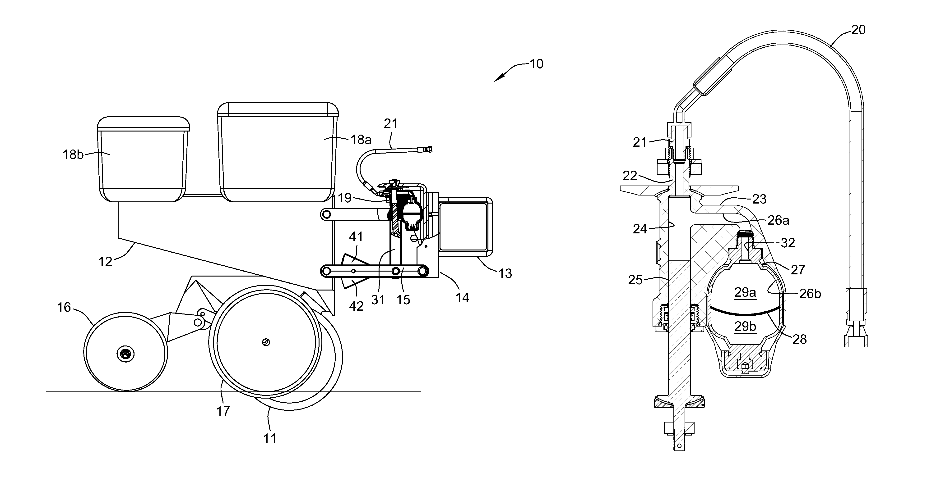
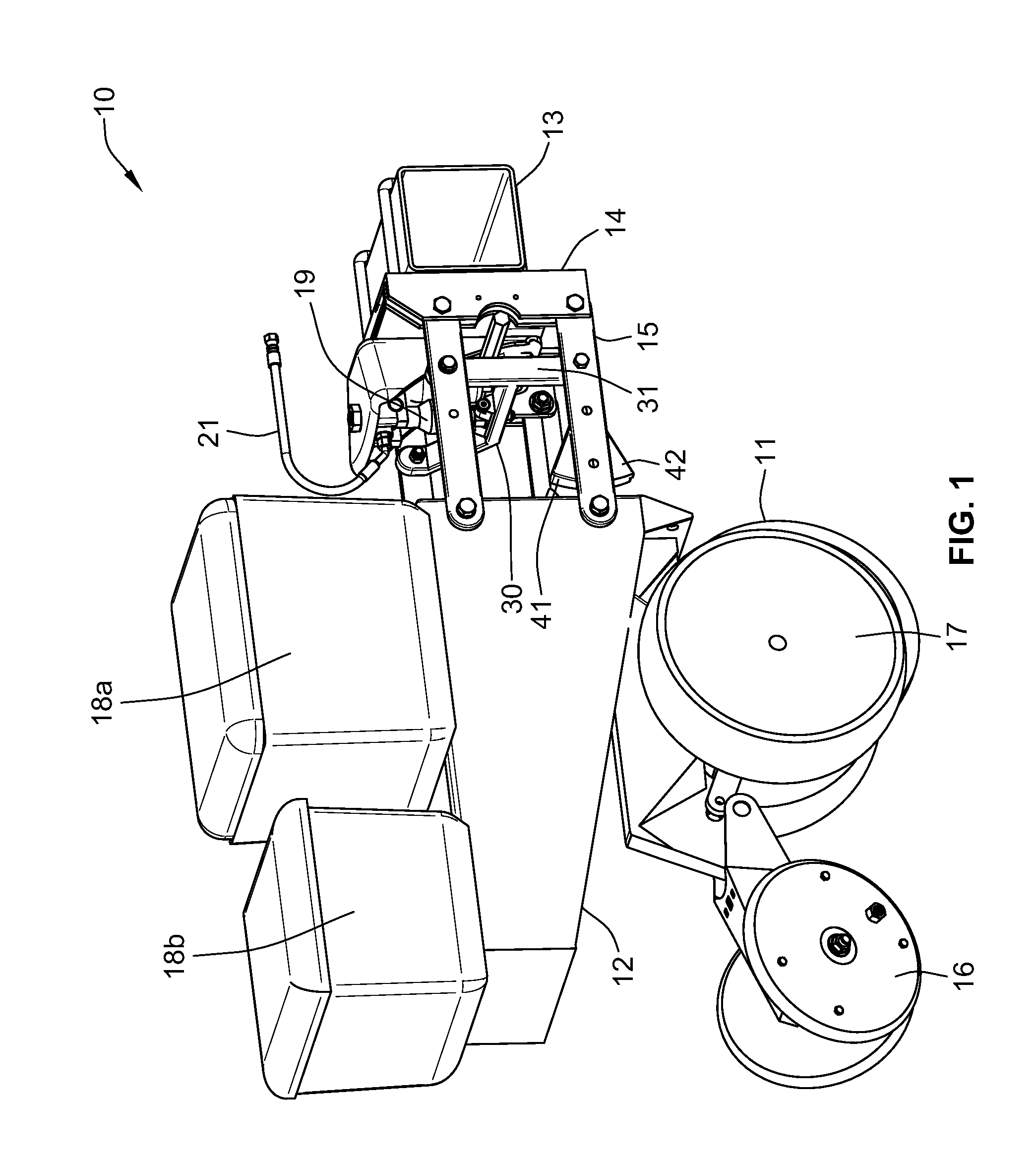
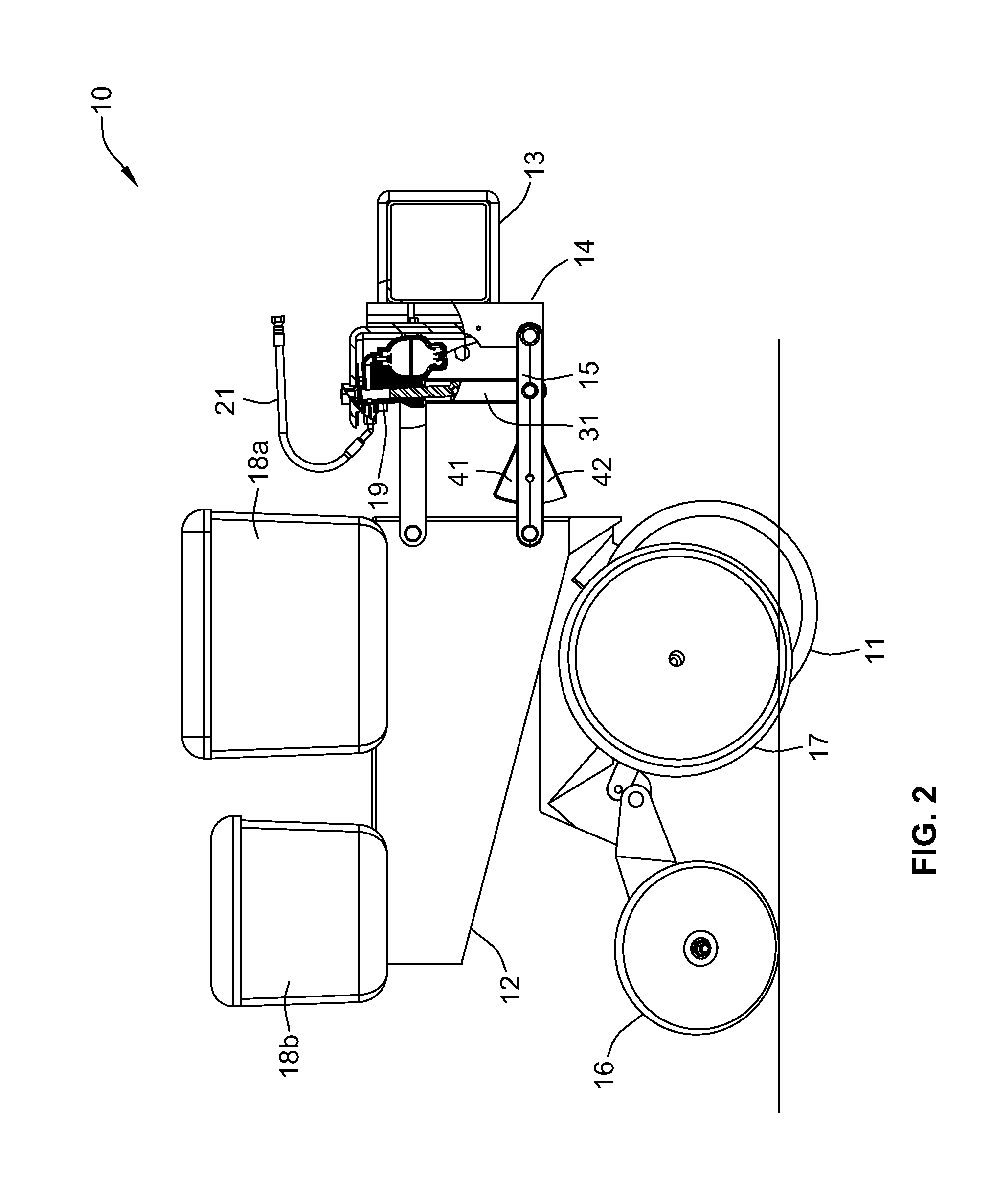
[0034]Turning now to the drawings, a planting row unit 10 includes a furrow-opening device for the purpose of planting seed or injecting fertilizer into the soil. In the illustrated embodiment, the furrow-opening device is a V-opener 11 formed by a pair of conventional tilted discs depending from the leading end of a row unit frame 12. It will be understood that other furrow-opening devices may be used. A conventional elongated hollow towing frame 13 (typically hitched to a tractor by a draw bar) is rigidly attached to the front frame 14 of a conventional four-bar linkage assembly 15 that is p...


PUM


Abstract

In one embodiment, an agricultural row unit for use with a towing frame hitched to a tractor includes an attachment frame adapted to be rigidly connected to the towing frame. A support member is pivotably coupled to the attachment frame to permit vertical pivoting movement of the support member relative to the attachment frame, and at least one furrow-closing device is mounted on the support member. A hydraulic cylinder is coupled to the support member for urging the row unit frame downwardly toward the soil. The hydraulic cylinder includes a movable ram extending into the cylinder, and a hydraulic-fluid cavity within the cylinder for receiving pressurized hydraulic fluid for urging the ram in a first direction that pivots the support member in a first vertical direction. An accumulator has a fluid chamber containing a pressurized gas for urging the ram in a second direction that pivots the support member in a second vertical direction.

Description

CROSS-REFERENCE TO RELATED APPLICATION[0001]This application is a continuation-in-part of U.S. patent application Ser. No. 12 / 882,627, filed Sep. 15, 2010, for “Row Unit for Agricultural Implement.”FIELD OF THE INVENTION[0002]The present invention relates to agricultural implements and, more particularly, to an agricultural row unit for use with agricultural implements such as planting row units.BACKGROUND OF THE INVENTION[0003]As an agricultural planter row unit travels across fields with variable soil types, soil moisture, residue levels and topography, it is difficult to maintain constant seed depth and other parameters due to changing conditions which would ideally require varying the row unit down force pressure. For example, farming with higher residue levels also requires higher row unit down force levels as row cleaners, coulters and other attachments require applied force to keep them in the ground and at consistent depths.[0004]At the same time, in many locations there are...

Claims


Application Information

Patent Timeline
Patent Type & Authority Patents(United States)
IPC IPC(8): A01B63/32A01B15/14A01B15/16A01B15/18A01B23/06A01B7/00A01B5/10
CPCA01C7/205A01B61/046
Inventor BASSETT, JOSEPH D.
Owner DAWN EQUIPMENT COMPANY
Why Eureka
Try Eureka