Fail-safe high velocity flow casing shoe

a high-speed flow, casing shoe technology, applied in the direction of drilling casings, wellbore/well accessories, pipes, etc., can solve the problems of difficulty in running intermediate and production casings, time spent attempting to work past obstructions, money wasted, etc., to minimize the ‘surge’ of wellbore pressure and low flow area

Active Publication Date: 2020-09-01
WWT NORTH AMERICA HLDG
View PDF23 Cites 0 Cited by
  • Summary
  • Abstract
  • Description
  • Claims
  • Application Information

AI Technical Summary

Benefits of technology

[0008]The present invention is a way to provide low flow area, high velocity flow out of the bottom of the casing shoe to clean the hole and wash through many downhole obstructions, including settled cuttings, caved in formation, and flows of tar or salt. The present invention also provides a means to allow unobstructed flow of fluid into the casing to minimize wellbore pressure ‘surge’ while running casing. The present invention also provides a means to convert the casing shoe to a large flow area out of the shoe if needed for pumping cement or LCM out of the shoe, or if the smaller high velocity nozzles become plugged.
[0009]The present invention is a casing shoe that has a one-way check valve or flapper valve that allows unobstructed flow into the casing through a large flow area centerline nozzle, but forces flow out through multiple, circumferentially spaced, small diameter nozzles. Flow out through the smaller nozzles causes a pressure differential between the inside and outside of the casing shoe that increases as flow rate increases. This pressure differential also serves to place a load that serves to close the check / flapper valve. The valve assembly includes tabs that support the flapper door section of the valve. At a pre-determined pressure differential, the tabs shear to allow the flapper door to open, greatly increasing the flow area, resulting in unrestricted flow of cement, LCM, or drilling fluid.
[0012]An embodiment uses the seal as a hinge, and is cast into place using an elastomeric material such as polyurethane. With an embodiment, no metallic materials are located within the drill out path that might damage the drill bit. Aluminum and steel in the drill out path can slow down the drill out process after the casing has been set and the operator continues drilling out of the casing and into the next hole section.

Problems solved by technology

Time spent attempting to work past an obstruction, is money wasted.
These problems can occur in offshore and onshore wells.
These types of wells are often drilled quickly, and as a result of the high inclination horizontal production zone pose a particular problem in fully cleaning cuttings from the wellbore.
As a result, operators sometimes encounter difficulties in running intermediate and production casing to the bottom of the wellbore.
Many deepwater wells in the Gulf of Mexico as well as some extended reach wells drilled from land based rigs experience zones with tar that can seep into the newly drilled wellbore, making it difficult to run casing through these areas.
There are ‘jetting’ shoes available, but these ‘jetting’ shoes need very large flow areas to be able to allow displaced fluid to enter the casing, and to circulate cement and large particulate lost circulation material (LCM) to be pumped through the shoe.
As a result, the total flow area is far too large to provide a true high velocity flow stream that would have any effect on downhole obstructions as mentioned above.
Some reamer shoes do have some smaller nozzles, but they also have limited ability to circulate cement or LCM if these nozzles become plugged rendering them vulnerable and ineffective in many circumstances.
Also there currently exists no means to work casing through areas of tar.
Often casing will not be able to work through tar flows because of the above requirements for a large flow area required to allow fluid to flow in from the bottom of the casing as a result of the fluid displaced by the casing while running into the hole.
If there is a large ‘surge’ effect caused by pressure buildup at the bottom of the wellbore, this could result in fracturing the formation and causing loss of well control.

Method used


Image

  • Fail-safe high velocity flow casing shoe
  • Fail-safe high velocity flow casing shoe
  • Fail-safe high velocity flow casing shoe

Examples


Embodiment Construction

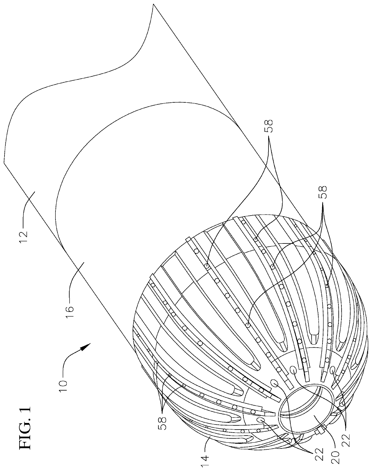
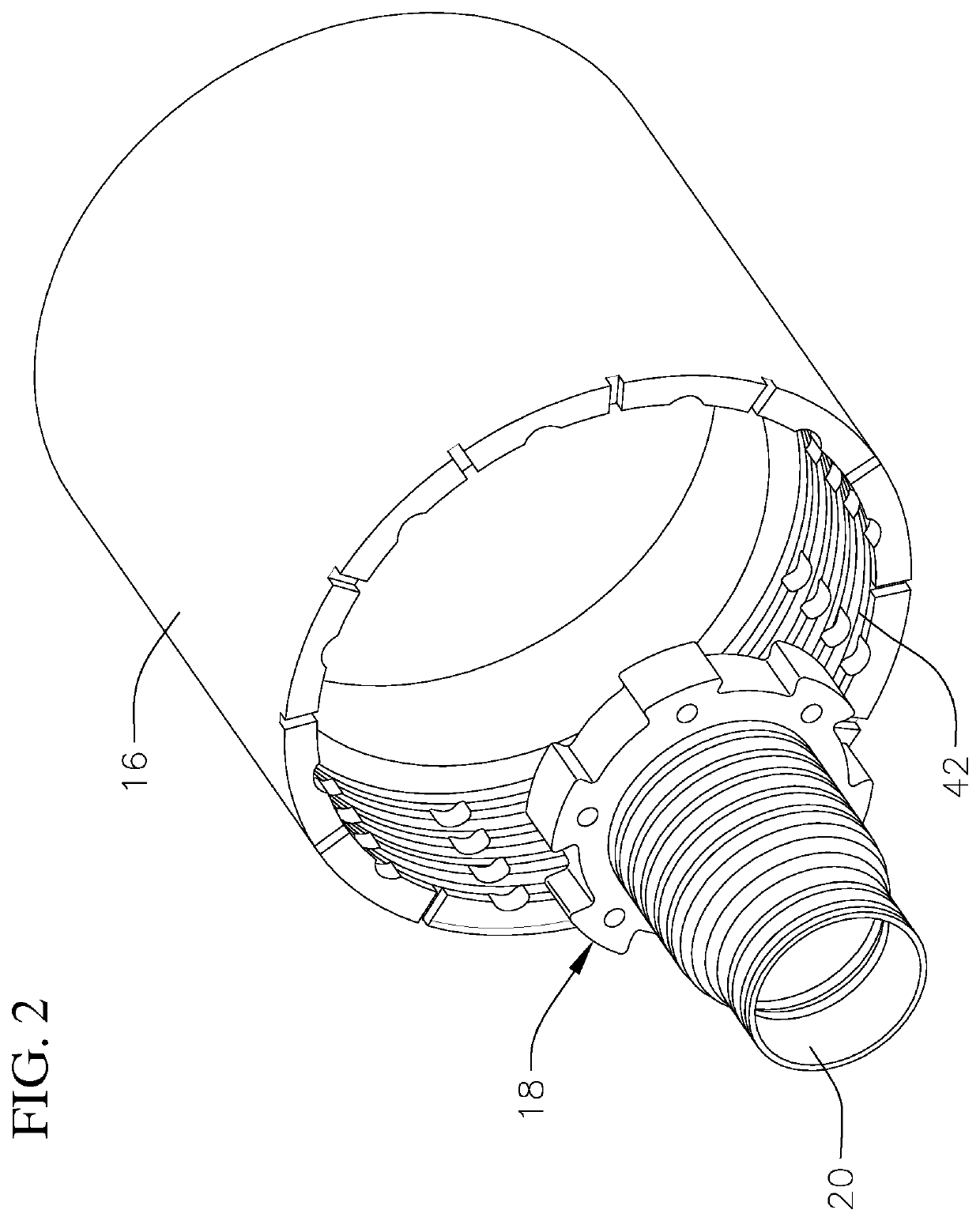
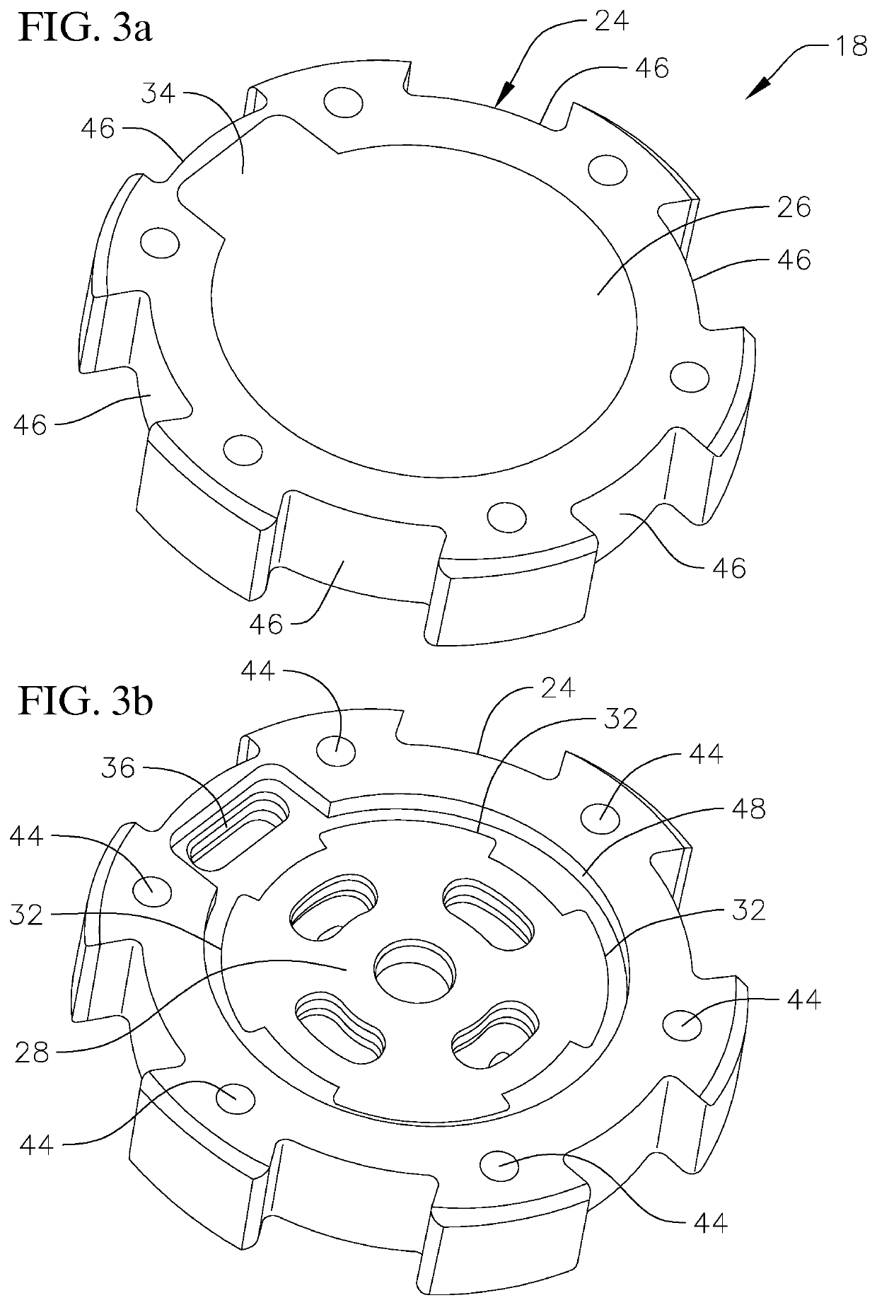
[0022]Referring to FIGS. 1-4, the present invention is a casing shoe 10 for attachment to the bottom of a wellbore casing 12 to provide low flow area, high-velocity flow out of the bottom of the casing shoe to clean the wellbore and wash through downhole obstructions. The casing shoe also provides a means to allow unobstructed flow of fluid into the casing to minimize wellbore pressure surge while running casing and provides a means to convert the casing shoe to a large flow area out of the shoe in needed for pumping cement or loss circulation material (LCM) out of the shoe, or if the smaller high-velocity nozzles become plugged. The casing shoe 10 includes a cast body portion 14 and a coupling portion 16. Positioned within the body portion is a one-way check valve or flapper valve assembly 18 that allows unobstructed flow into the casing through a large flow area centerline nozzle 20, but forces flow out through multiple, circumferentially spaced, small diameter nozzles 22. Flow ou...


PUM


Abstract

A casing shoe having a composite body portion, a coupling portion attached to one end of the body portion, and a one-way check valve assembly positioned in the body portion, the valve assembly and body portion having a centerline nozzle and a plurality of circumferentially spaced smaller diameter nozzles positioned around the centerline nozzle.

Description

CROSS-REFERENCE TO RELATED APPLICATION(S)[0001]This application claims priority to and the benefit of U.S. Provisional Application No. 62 / 439,766 filed Dec. 28, 2016, the contents of which are incorporated herein.BACKGROUND OF THE INVENTION[0002]When drilling oil and gas wells, it is important to have pressure containment, formation isolation, and well integrity to have a well that is safe and productive. Therefore, it is critical to have casing run to the desired depth and cemented in place in the wellbore to provide an adequate pressure boundary for well integrity. Also, to minimize well construction costs, it is also important to minimize the time needed to run casing to the desired setting depth. Time spent attempting to work past an obstruction, is money wasted. Downhole obstructions can consist of settled cuttings, formation caving due to wellbore instability, mud weight material sag, salt flows, or tar flows. These problems can occur in offshore and onshore wells.[0003]A majo...

Claims


Application Information

Patent Timeline
Patent Type & Authority Patents(United States)
IPC IPC(8): E21B41/00E21B17/14E21B43/10E21B33/14
CPCE21B17/14E21B41/0078E21B33/14E21B43/106
Inventor MITCHELL, SARAHTROWBRIDGE, ANDREW
Owner WWT NORTH AMERICA HLDG
Why Eureka
Try Eureka