Variable purge orifice assembly

a technology of purge orifice and variable size, which is applied in the direction of combustion air/fuel air treatment, machines/engines, fuel injecting pumps, etc., to achieve the effect of low flow resolution

Inactive Publication Date: 2005-12-22
DELPHI TECH INC
View PDF20 Cites 4 Cited by
  • Summary
  • Abstract
  • Description
  • Claims
  • Application Information

AI Technical Summary

Benefits of technology

[0006] One advantage of the present invention is that a variable purge orifice assembly is provided for an evaporative emission system of a vehicle. Another advantage of the present invention is that the variable purge orifice assembly incorporates a regulating device for metering purge flow serially with a pulsewidth modulated solenoid, which is optional. Yet another advantage of the present invention is that the variable purge orifice assembly achieves flow regulation by utilizing engine manifold vacuum to actuate the regulating device. Still another advantage of the present invention is that the variable purge orifice assembly maximizes the orifice at low manifold vacuum such that the solenoid flow is unrestricted. A further advantage of the present invention is that the variable purge orifice assembly minimizes the orifice at high vacuum manifold such that the solenoid flow is restricted, allowing the purge solenoid flow rate to be increased without losing low flow resolution.
[0007] Other features and advantages of the present invention will be readily appreciated, as the same becomes better understood, after reading the subsequent description taken in conjunction with the accompanying drawings.

Problems solved by technology

However, this allows the highest purge flows at low engine airflows and the lowest purge flow at the highest engine airflows, which is undesired.

Method used


Image

  • Variable purge orifice assembly
  • Variable purge orifice assembly
  • Variable purge orifice assembly

Examples


Embodiment Construction

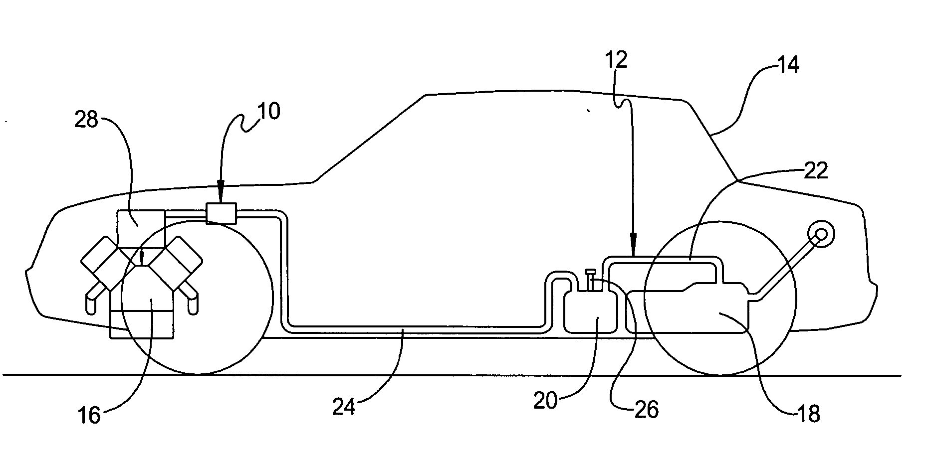
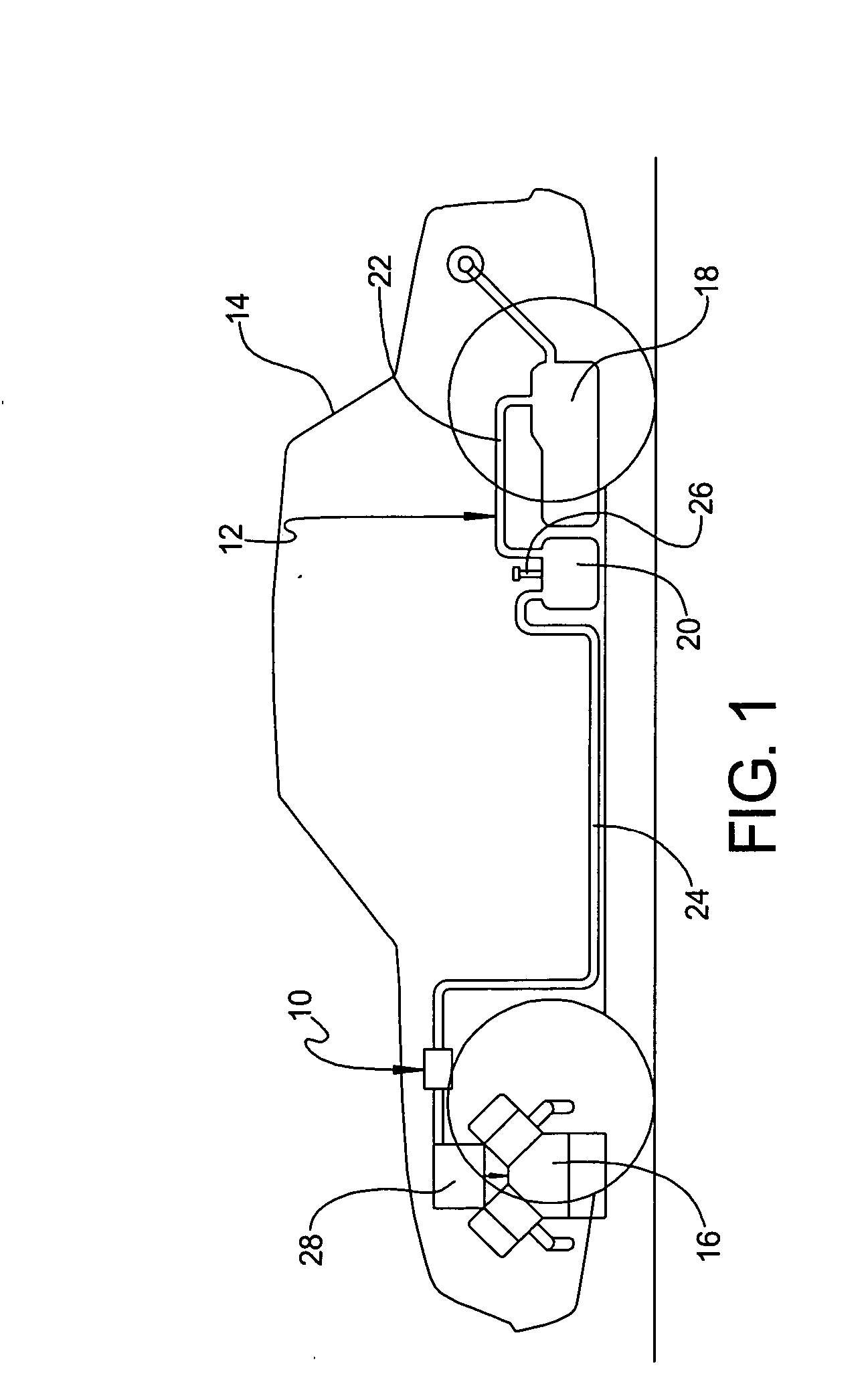
[0011] Referring to the drawings and in particular FIG. 1, one embodiment of a variable purge orifice assembly 10, according to the present invention, is shown for an evaporative emission system, generally indicated at 12, for a vehicle 14. The vehicle 14 includes an engine 16 and a fuel tank 18 for supplying fuel to the engine 16. The vehicle 14 also includes the evaporative emission system 12 interconnecting the engine 16 and the fuel tank 18. It should be appreciated that the vehicle 14 is conventional and known in the art.

[0012] The evaporative emission system 12 includes a vapor canister 20 holding a canister bed (not shown) to adsorb hydrocarbon or fuel vapor while allowing air to pass to and from the fuel tank 18. The vapor canister 20 has a first tube 22 for communicating with the fuel tank 18, a second tube 24 communicating with and being purged by the engine 16 and a third tube 26 communicating with the outside environment. It should be appreciated that the vapor canister...


PUM


Abstract

A variable purge orifice assembly for an evaporative emission system of a vehicle includes a housing for fluid connection to a vapor canister and a purge solenoid of the evaporative emission system. The housing has a purge orifice therein. The variable purge orifice assembly also includes a regulating device connected to the housing and for connection to an engine of the vehicle. The regulating device is actuated by manifold vacuum from the engine to vary flow of fuel vapor through the purge orifice from the vapor canister to the purge solenoid.

Description

TECHNICAL FIELD [0001] The present invention relates generally to evaporative emission systems for vehicles and, more particularly, to a variable purge orifice assembly for an evaporative emission system of a vehicle. BACKGROUND OF THE INVENTION [0002] It is known to provide a fuel system for a vehicle having a fuel tank to hold fuel to be used by an engine of the vehicle. It is also known to provide an evaporative emission system for a fuel system of the vehicle to recover fuel vapor. Typically, the evaporative emission system includes a vapor canister remotely mounted such as in an engine compartment of the vehicle and operatively connected by separate external valves and lines to a fuel tank. [0003] Typically, purge solenoid valves are operated between manifold vacuum and pressure of the evaporative emission system, which is approximately atmospheric pressure. However, this allows the highest purge flows at low engine airflows and the lowest purge flow at the highest engine airfl...

Claims


Application Information

Patent Timeline
Patent Type & Authority Applications(United States)
IPC IPC(8): F02M25/08F02M33/04
CPCF02M25/0836
Inventor ROBERTSON, WILLIAM R.COVERT, CHARLES H.PADDOCK, GORDON R.
Owner DELPHI TECH INC
Why Eureka
Try Eureka