Method of radially expanding a tubular element
a tubular element and radial expansion technology, applied in the direction of drilling pipes, drilling casings, borehole/well accessories, etc., to achieve the effect of increasing the length of the expanded tubular section
- Summary
- Abstract
- Description
- Claims
- Application Information
AI Technical Summary
Benefits of technology
Problems solved by technology
Method used
Image
Examples
first embodiment
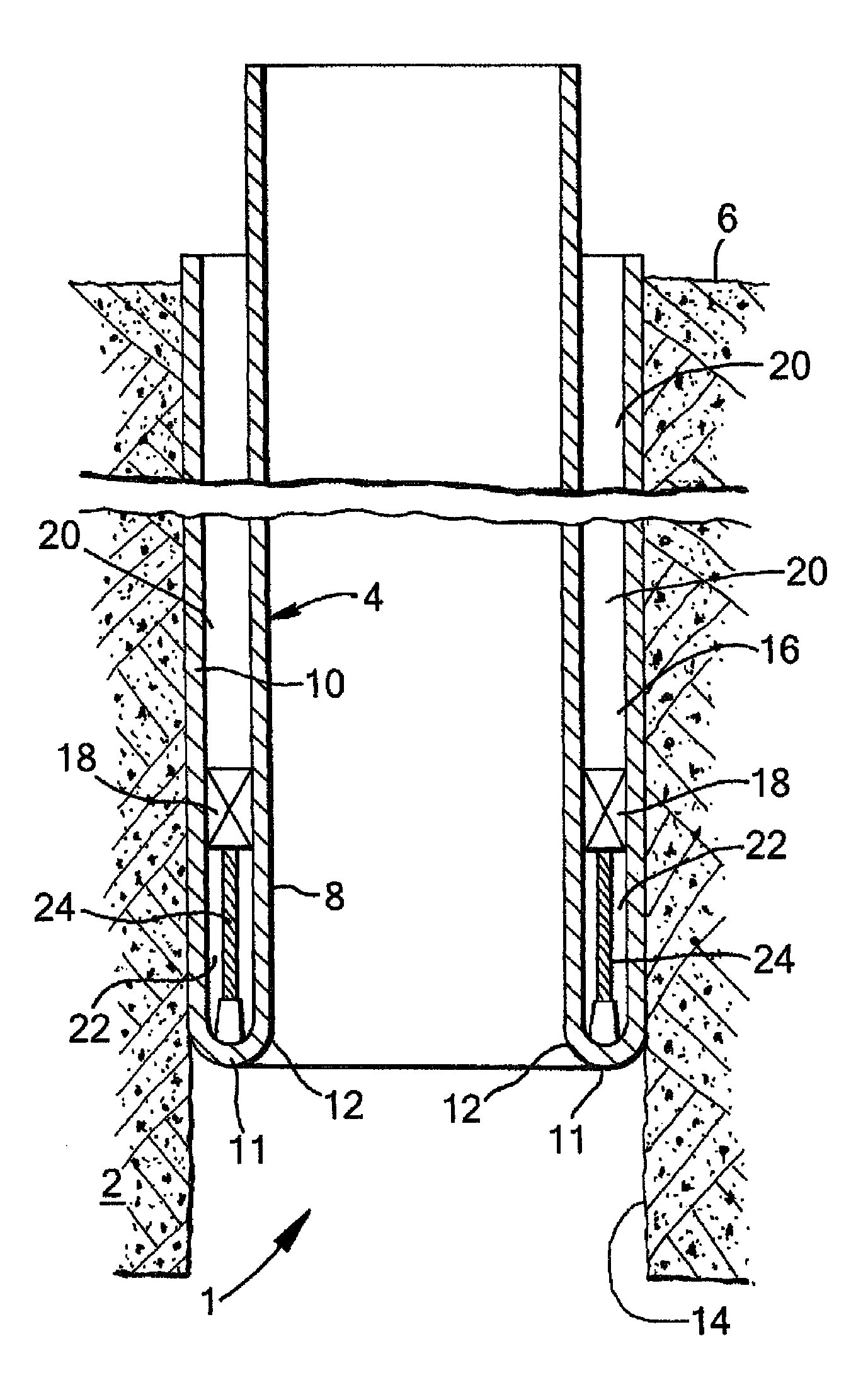
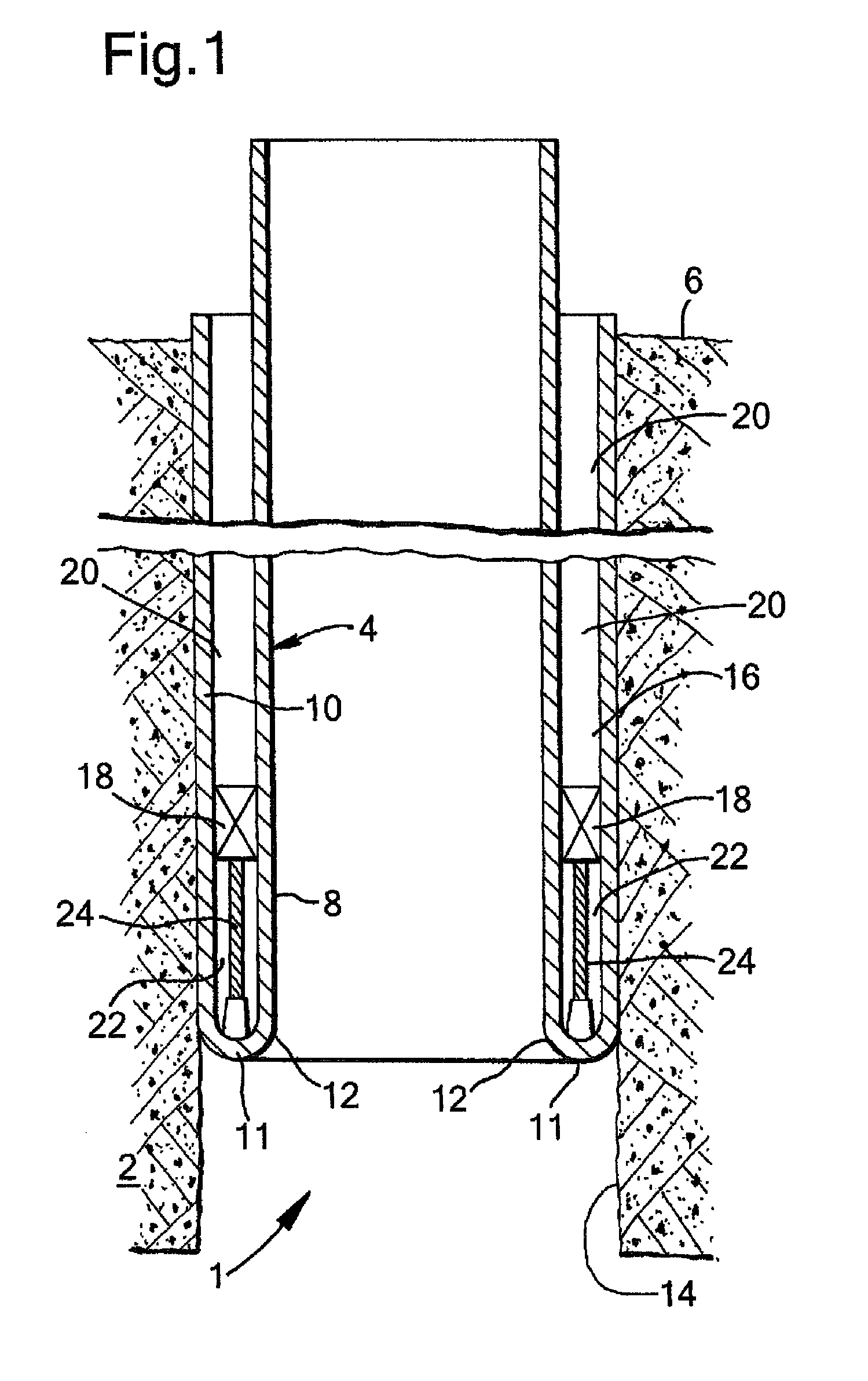
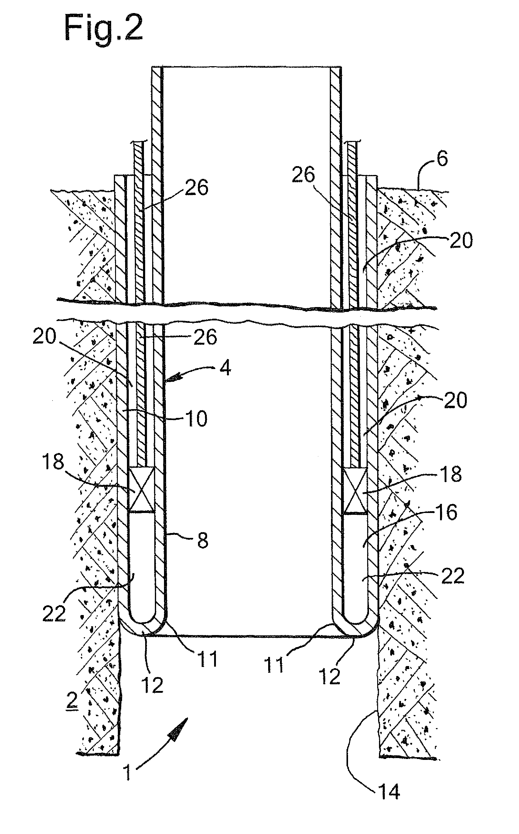
[0034]Referring to FIG. 1 there is shown the first embodiment comprising a wellbore 1 extending into an earth formation 2, and a tubular element in the form of liner 4 extending from surface 6 downwardly into the wellbore 1. The liner 4 has been partially radially expanded by eversion of the wall of the liner whereby a radially expanded tubular section 10 of the liner 4 has been formed, which has an outer diameter substantially equal to the wellbore diameter. A remaining tubular section 8 of the liner 4 extends concentrically within the expanded tubular section 10.
[0035]The wall of the liner 4 is, due to eversion at its lower end, bent radially outward and in axially reverse (i.e. upward) direction so as to form a U-shaped lower section 11 of the liner interconnecting the remaining liner section 8 and the expanded liner section 10. The U-shaped lower section 11 of the liner 4 defines a bending zone 12 of the liner.
[0036]The expanded liner section 10 is axially fixed to the wellbore ...
third embodiment
[0040]In FIG. 5 is shown a modified seal element 18′ for use in the The modified seal element 18′ is substantially similar to the seal element 18, except that the modified seal element 18′ is additionally provided with a gripper device 29 connected to, or integrally formed with, the seal element 18. The gripper device 29 is biased against the expanded tubular section 10, and functions to prevent upward movement of the seal element 18′ relative to the expanded tubular section 10.
fourth embodiment
[0041]In FIGS. 6-8 is shown the fourth embodiment, whereby a series of annular flexible seals 30, 31, 32, 33, 34 are connected to the radially outer surface of the remaining liner section 8 or to the radially inner surface of the expanded liner section 10. It is to be understood that one edge 40 of each flexible seal 30, 31, 32, 33, 34 is connected either to the remaining liner section 8 or to the expanded liner section 10, while the other edge 42 of the flexible seal is free from either liner section 8, 10. The free edge 42 of each flexible seal 30, 32, 34 that is connected to the remaining liner section 8, is adapted to move against the expanded liner section 10 and thereby seal against the expanded liner section 10, upon a fluid pressure in the annular space 16, above the flexible seal 30, 32, 34, exceeding a fluid pressure in the annular space 16, below the flexible seal 30, 32, 34. Also, the free edge 42 of each flexible seal 31, 33 that is connected to the expanded liner secti...
PUM
 Abstract
Description
Claims
Application Information
 - R&D
- Intellectual Property
- Life Sciences
- Materials
- Tech Scout
- Unparalleled Data Quality
- Higher Quality Content
- 60% Fewer Hallucinations
Browse by: Latest US Patents, China's latest patents, Technical Efficacy Thesaurus, Application Domain, Technology Topic, Popular Technical Reports.
© 2025 PatSnap. All rights reserved.Legal|Privacy policy|Modern Slavery Act Transparency Statement|Sitemap|About US| Contact US: help@patsnap.com


