Method of radially expanding a tubular element

a tubular element and radial expansion technology, applied in the direction of prosthesis, blood vessels, borehole/well accessories, etc., can solve the problems of high friction force that needs to be overcome, the expansioner becomes stuck in the tubular element, and the cross-sectional wellbore size available for oil and gas production, etc., to reduce the tendency of buckling

Active Publication Date: 2011-11-15
SHELL OIL CO
View PDF13 Cites 12 Cited by
  • Summary
  • Abstract
  • Description
  • Claims
  • Application Information

AI Technical Summary

Benefits of technology

[0010]Thus, the tubular element is effectively turned inside out during the bending process. The bending zone of a respective layer defines the location where the bending process takes place. By inducing the bending zone of each layer to move in an axial direction along the tubular element it is achieved that the tubular element is progressively expanded without the need for an expander that is pushed, pulled or pumped through the tubular element.
[0011]Furthermore, with the method of the invention it is achieved that the required force for inverting the tubular element, is significantly lower than the force necessary to invert a tubular element having a wall of similar wall thickness, made of a single wall layer rather than separate layers. Nevertheless, the burst strength and collapse strength of the tubular element inverted with the method of the invention, are comparable to those of the tubular element having a wall made of a single layer.
[0016]If the bending zone is located at a lower end of the tubular element, whereby the remaining tubular section is axially shortened at a lower end thereof due to the movement of the bending zone, it is preferred that the remaining tubular section is axially extended at an upper end thereof in correspondence with said the shortening at the lower end thereof. The remaining tubular section gradually shortens at its lower end due to continued reverse bending of the wall. Therefore, by extending the remaining tubular section at its upper end to compensate for shortening at its lower end, the process of reverse bending the wall can be continued until a desired length of the expanded tubular section is reached. The remaining tubular section can be extended at its upper end, for example, by connecting a tubular portion to said upper end in any suitable manner such as by welding. Alternatively, the remaining tubular section can be provided in the form of a coiled tubing which is unreeled from a reel and gradually inserted into the wellbore. Thus, the coiled tubing is extended at its upper end by unreeling from the reel.
[0017]As a result of forming the expanded tubular section around the remaining tubular section, an annular space is formed between the unexpanded and expanded tubular sections. To increase the collapse resistance of the expanded tubular section, a pressurized fluid can be inserted into the annular space. The fluid pressure can result solely from the weight of the fluid column in the annular space, or in addition also from an external pressure applied to the fluid column.
[0021]To reduce any buckling tendency of the unexpanded tubular section during the expansion process, the remaining tubular section advantageously is centralised within the expanded section by any suitable centralising means.

Problems solved by technology

As a result, the cross-sectional wellbore size that is available for oil and gas production, decreases with depth.
Such method can lead to high friction forces that need to be overcome, between the expander and the inner surface of the tubular element.
Also, there is a risk that the expander becomes stuck in the tubular element.

Method used


Image

  • Method of radially expanding a tubular element
  • Method of radially expanding a tubular element
  • Method of radially expanding a tubular element

Examples


Embodiment Construction

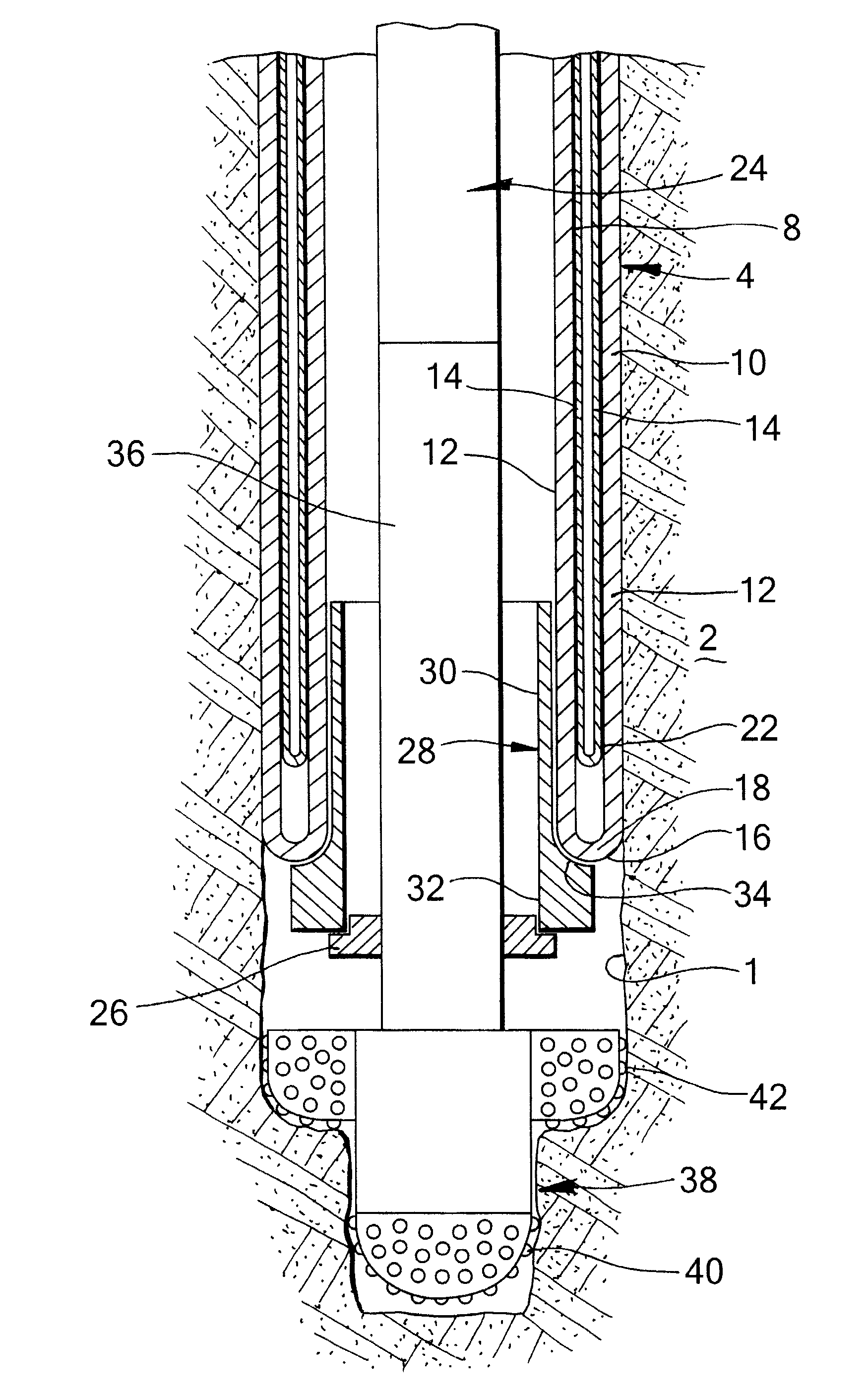
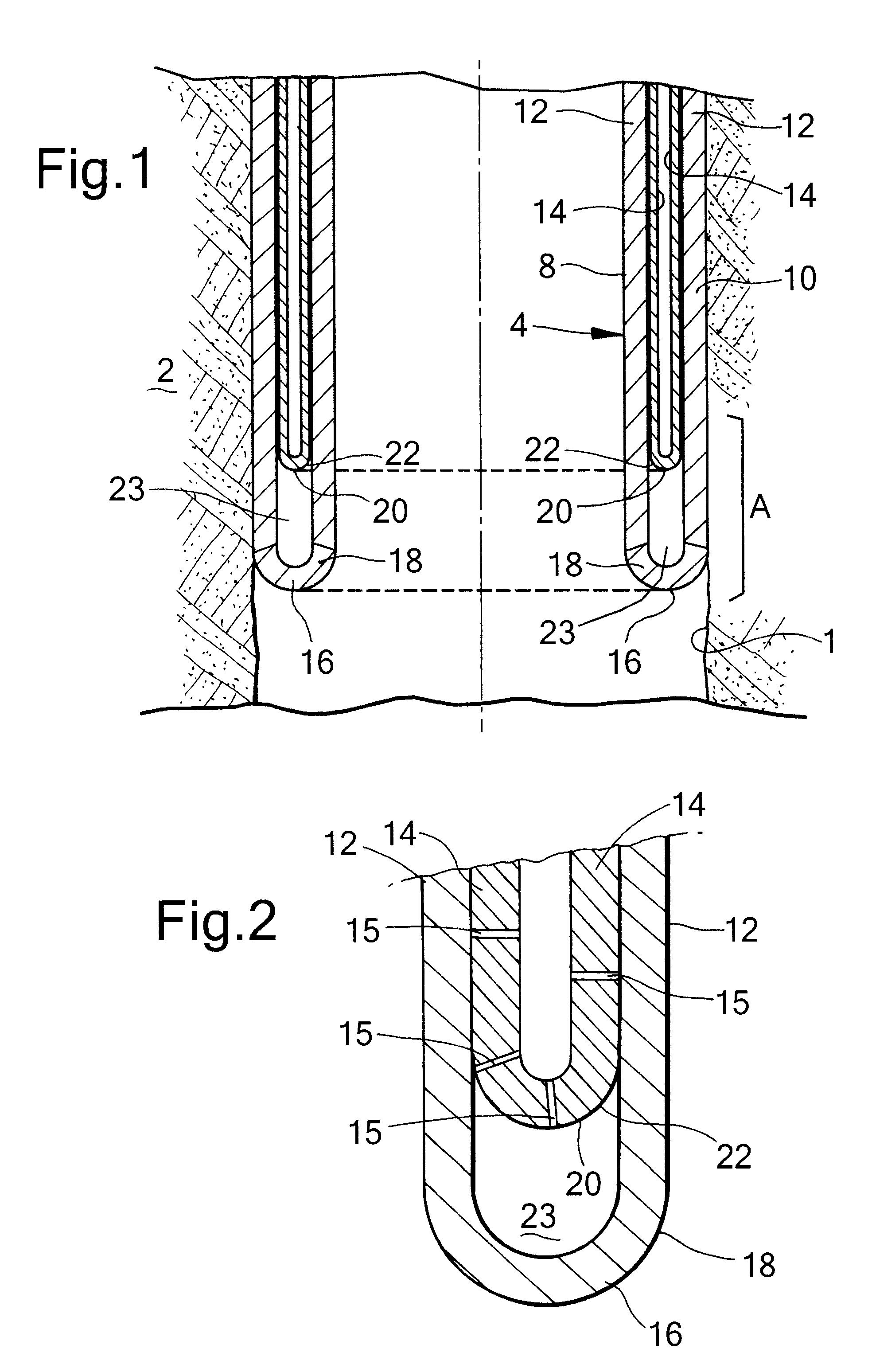
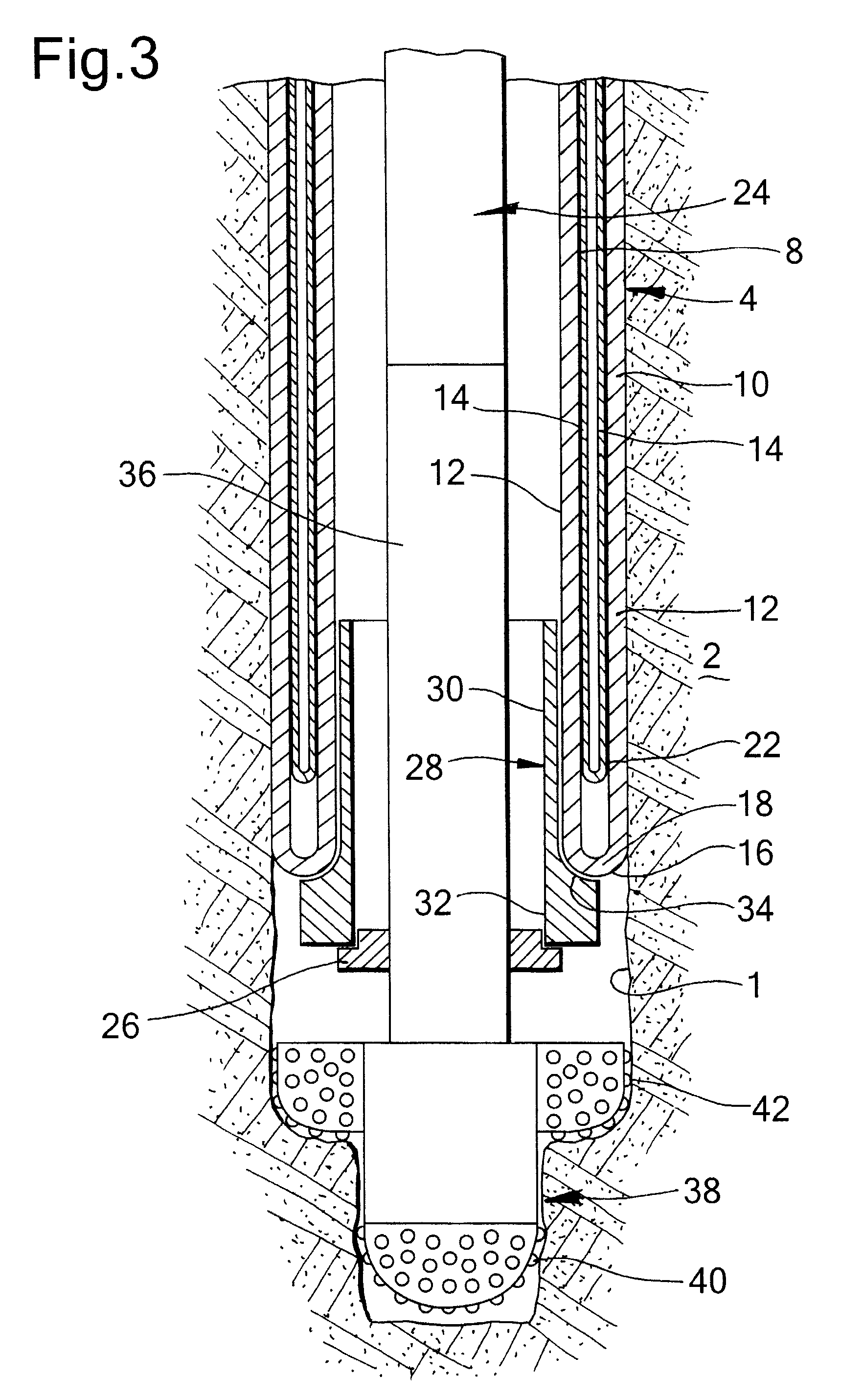
[0027]Referring to FIGS. 1 and 2 there is shown a system comprising a wellbore 1 extending into an earth formation 2, and a tubular element in the form of liner 4 extending downwardly into the wellbore 1. The liner 4 has been partially radially expanded by eversion of the wall of the liner whereby a radially expanded tubular section 10 of the liner 4 has been formed. A remaining tubular section 8 of the liner 4 extends concentrically within the expanded tubular section 10. The wall of the liner 4 includes a first layer 12 and a second layer 14, both of steel, whereby the second layer 14 extends around the first layer 12 at the remaining liner section 8. Thus, as a result of the eversion process, the second layer 14 extends inside the first layer 12 at the expanded liner section 10.

[0028]The first and second layers 12, 14 are separable from each other. The layers 12, 14 can be held together, for example, by a suitable pre-stress in circumferential direction. That is to say, at the re...


PUM


Abstract

The invention relates to a method of radially expanding a tubular element extending into a wellbore formed in an earth formation, the tubular element including a first layer and a second layer extending around the first layer, said layers being separable from each other. The method comprises inducing each layer to bend radially outward and in an axially reverse direction so as to form an expanded tubular section extending around a remaining tubular section of the tubular element, wherein each layer has a respective bending zone in which the bending occurs, and increasing the length of the expanded tubular section by inducing the respective bending zones of the layers to move in an axial direction relative to the remaining tubular section. The layers in the respective bending zones are separate from each other so as to define an axial space between the layers.

Description

RELATED CASES[0001]The present application claims priority to PCT Application EP2008 / 064512, filed 27 Oct. 2008, which in turn claims priority from European Application EP07119460.9, filed 29 Oct. 2007.FIELD OF THE INVENTION[0002]The present invention relates to a method of radially expanding a tubular element in a wellbore.BACKGROUND OF THE INVENTION[0003]The technology of radially expanding tubular elements in wellbores is increasingly applied in the industry of oil and gas production from subterranean formations. Wellbores are generally provided with one or more casings or liners to provide stability to the wellbore wall, and / or to provide zonal isolation between different earth formation layers. The terms “casing” and “liner” refer to tubular elements for supporting and stabilising the wellbore wall, whereby it is generally understood that a casing extends from surface into the wellbore and that a liner extends from a downhole location further into the wellbore. However, in the ...

Claims


Application Information

Patent Timeline
Patent Type & Authority Patents(United States)
IPC IPC(8): E21B19/00
CPCE21B43/103
Inventor KRIESELS, PETRUS CORNELISMACK, ROBERT DONALDSHUSTER, MARK MICHAEL
Owner SHELL OIL CO
Why Eureka
Try Eureka