
Method of expanding a tubular element in a wellbore

a tubular element and wellbore technology, applied in the direction of drilling pipes, rotary drilling, borehole/well accessories, etc., can solve the problems of high friction between the expander and the tubular element, the expander becomes stuck in the tubular element, and the cross-sectional wellbore size available for oil and gas production, etc., to achieve effective inside rotation, increase fluid pressure, and control the diameter of the expanded tubular section

Inactive Publication Date: 2013-04-30
SHELL OIL CO
View PDF9 Cites 2 Cited by
  • Summary
  • Abstract
  • Description
  • Claims
  • Application Information

AI Technical Summary

Benefits of technology

The patent text describes a way to expand a tubular section in a wellbore without needing an expander. This is done by moving the tubular section downward, which causes it to expand and form a casing or liner in the wellbore. The technical effect of this method is to provide a more efficient and effective way to expand tubular sections in wellbores.

Problems solved by technology

As a result, the cross-sectional wellbore size that is available for oil and gas production, decreases with depth.
Such method can lead to high friction forces between the expander and the tubular element.
Also, there is a risk that the expander becomes stuck in the tubular element.

Method used


Image

  • Method of expanding a tubular element in a wellbore
  • Method of expanding a tubular element in a wellbore
  • Method of expanding a tubular element in a wellbore

Examples


Embodiment Construction

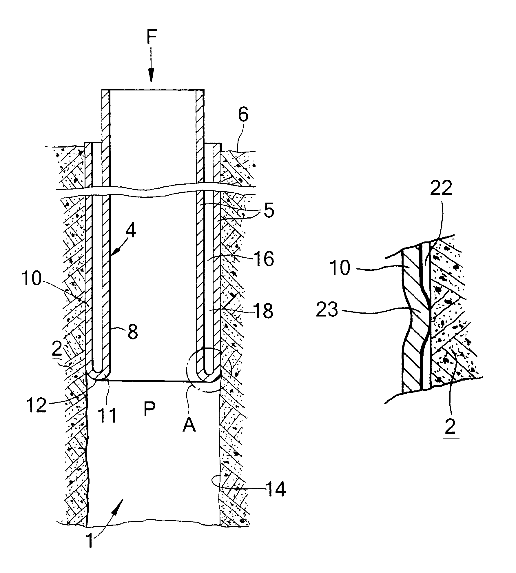
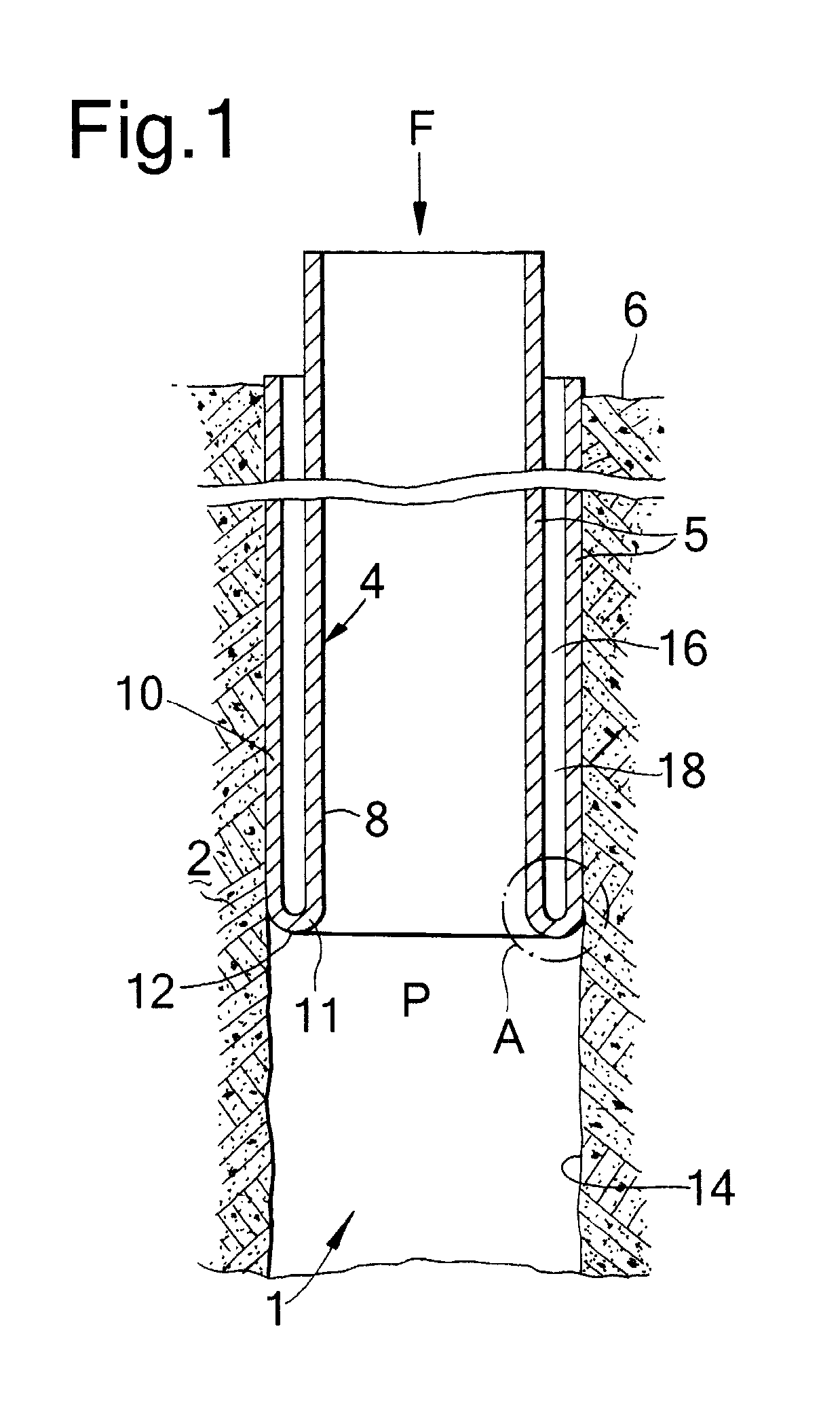
[0030]Referring to FIG. 1 there is shown a wellbore system whereby a wellbore 1 extends into an earth formation 2, and a tubular element in the form of liner 4 extends from surface downwardly into the wellbore 1. The liner 4 has been partially radially expanded by eversion of its wall 5 whereby a radially expanded tubular section 10 of the liner 4 has been formed of outer diameter substantially equal to the wellbore diameter. A remaining tubular section of the liner 4, in the form of unexpanded liner section 8, extends from surface 6 concentrically into the expanded tubular section 10.

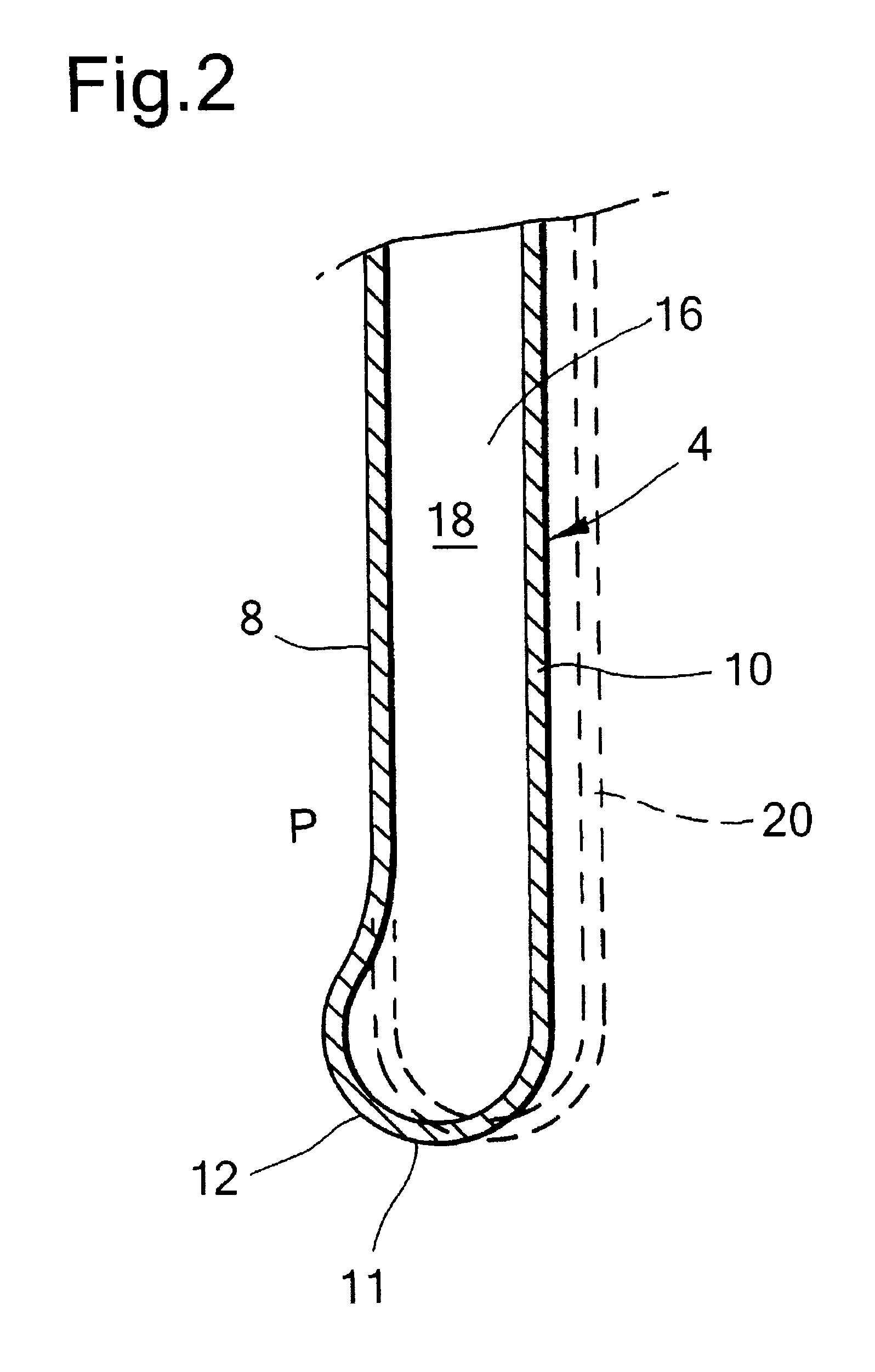
[0031]The wall 5 of the liner 4 is, due to eversion at its lower end, bent radially outward and in axially reverse (i.e. upward) direction so as to form a U-shaped lower section 11 of the wall 5 interconnecting the unexpanded liner section 8 and the expanded liner section 10. The U-shaped lower section 11 of the liner 4 defines a bending zone 12 of the liner.

[0032]The expanded liner section 10 is axial...


PUM


Abstract

A method of radially expanding a tubular element in a wellbore formed in an earth formation comprises arranging the tubular element in the wellbore such that a lower end portion of the wall of the tubular element extends radially outward and in an axially reverse direction so as to form an expanded tubular section extending around a remaining tubular section of the tubular element, whereby an annulus is defined between said expanded and remaining tubular sections, and axially extending the expanded tubular section by moving the remaining tubular section downward relative to the expanded tubular section so that said lower end portion of the wall bends radially outward and in an axially reverse direction. A diameter of the expanded tubular section is controlled by controlling a fluid pressure in the annulus.

Description

PRIORITY CLAIM[0001]The present application claims priority to PCT Application EP2008 / 067294, filed 11 Dec. 2008, which in turn claims priority from European Application EP07123104.7, filed 13 Dec. 2007.TECHNICAL FIELD OF THE INVENTION[0002]The present invention relates to a method of radially expanding a tubular element in a wellbore formed into an earth formation.BACKGROUND OF THE INVENTION[0003]The technology of radially expanding tubular elements in wellbores finds increasing application in the industry of oil and gas production from subterranean formations. Wellbores are generally provided with one or more casings or liners to provide stability to the wellbore wall, and / or to provide zonal isolation between different earth formation layers. The terms “casing” and “liner” refer to tubular elements for supporting and stabilising the wellbore wall, whereby it is generally understood that casing extends from surface into the wellbore and that a liner extends from a certain depth fu...

Claims


Application Information

Patent Timeline
Patent Type & Authority Patents(United States)
IPC IPC(8): E21B17/00
CPCE21B43/103
Inventor VAN NIEUWKOOP, PIETER
Owner SHELL OIL CO
Learn More