Vehicle and mast mounting assembly therefor

a technology for mounting assemblies and vehicles, applied in the direction of machine supports, collapsible antennas, building repairs, etc., can solve the problems of increasing the height or weight of the vehicle, prone to cumbersomeness,

Active Publication Date: 2012-10-02
THE UNITED STATES OF AMERICA AS REPRESENTED BY THE SECRETARY OF THE NAVY
View PDF54 Cites 222 Cited by
  • Summary
  • Abstract
  • Description
  • Claims
  • Application Information

AI Technical Summary

Problems solved by technology

The vehicle mounted masts tend to be cumbersome and raise the vehicle height or weight substantially.

Method used


Image

  • Vehicle and mast mounting assembly therefor
  • Vehicle and mast mounting assembly therefor
  • Vehicle and mast mounting assembly therefor

Examples


Embodiment Construction

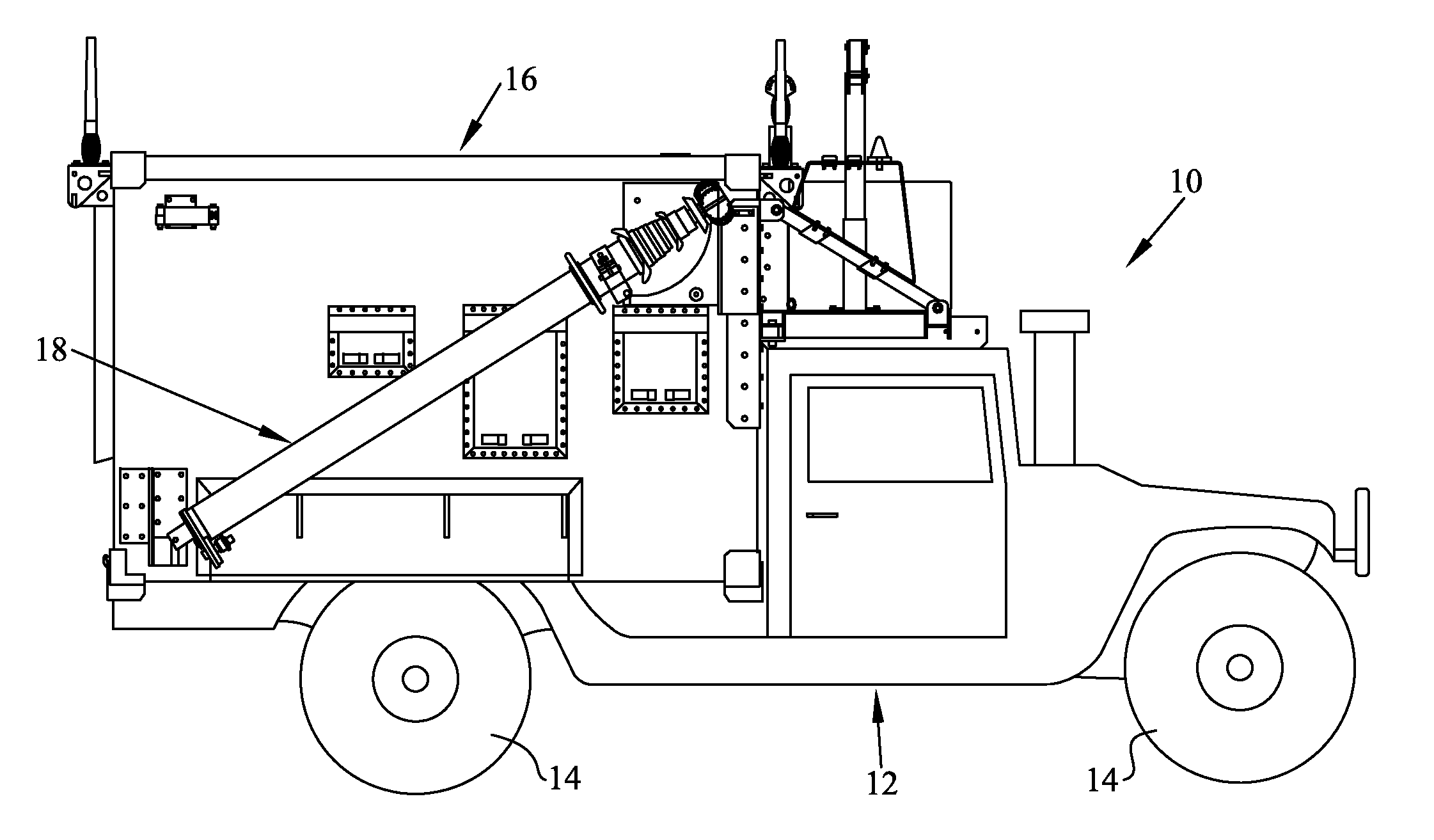
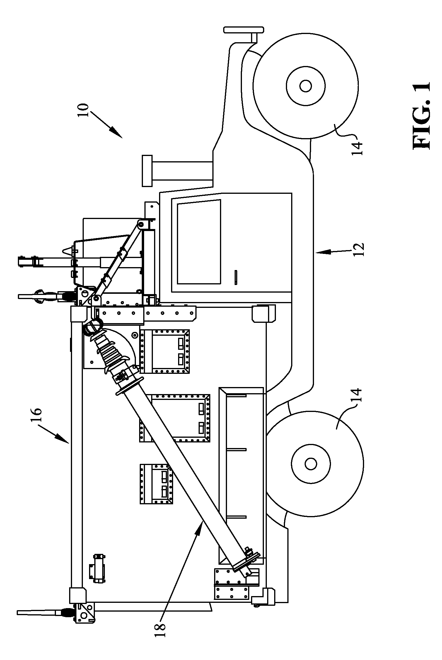
[0025]With reference first to FIG. 1, a vehicle 10 is disclosed which as disclosed is depicted as a truck, and more particularly as a military vehicle. It should be understood that the disclosure is equally applicable to commercial vehicles for use, for example, in radio or TV broadcasting or in any other application in which an extendable mast is used.

[0026]As shown, vehicle 10 comprises a frame 12, and ground engaging members 14 which support the frame 12. As depicted, the ground engaging members are shown as tires and wheels, however it should be understood that other ground engaging members such as tracks or skis could be employed. The invention is equally applicable to any water flotation devices. As shown, a shelter assembly 16 is supported by the vehicle frame 12 and includes a mast assembly 18 which will be described in greater detail herein.

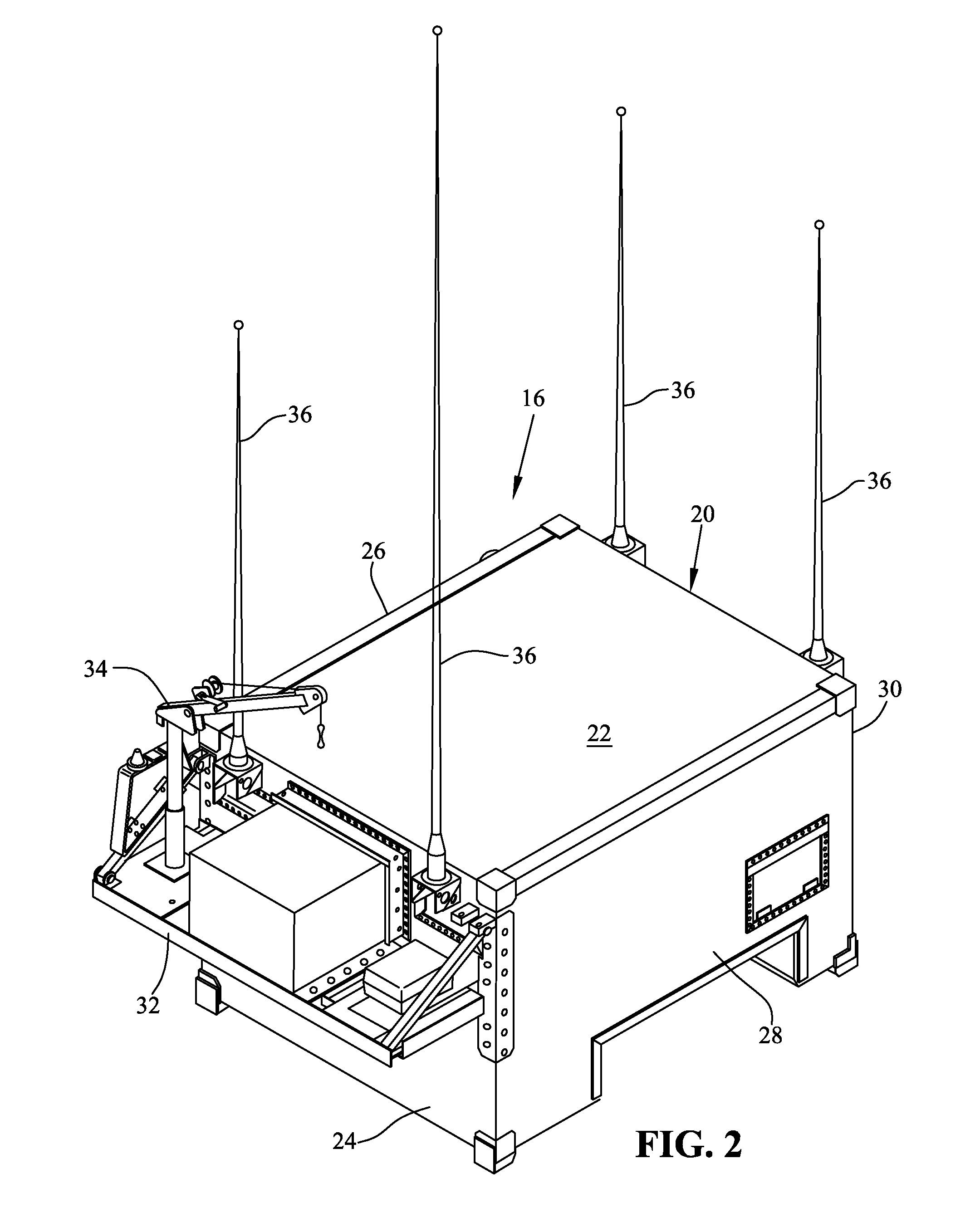
[0027]With respect now to FIGS. 2 and 3, shelter assembly 16 is shown in greater detail. Shelter assembly 16 includes an enclosure 20 h...


PUM

PropertyMeasurementUnit
heightaaaaaaaaaa
lengthaaaaaaaaaa
weightaaaaaaaaaa

Abstract

A vehicle is disclosed having a mast assembly mounted to a sidewall of the vehicle. The mast is pivotally mounted and can be held in a first stowed position by way of a first clamp member. The mast is pivotal relative to the sidewall, to an essentially vertical and erect position, and held in the second position by way of a second clamp.

Description

CROSS-REFERENCE TO RELATED APPLICATIONS[0001]The present application claims priority to U.S. Provisional Patent Application Ser. No. 61 / 291,694, filed Dec. 31, 2009, entitled “VEHICLE AND MAST MOUNTING ASSEMBLY THEREFOR,” the disclosure of which is expressly incorporated by reference herein. The present application is also related to U.S. patent application Ser. No. 12 / 696,778, filed Jan. 29, 2010, entitled “PROTECTIVE MEMBERS FOR A SIGNAL INTERFACE ASSEMBLY”, U.S. patent application Ser. No. 12 / 696,861, filed Jan. 29, 2010, entitled “COMMUNICATIONS VEHICLE”, and U.S. patent application Ser. No. 12 / 696,787, filed Jan. 29, 2010, entitled “MODULAR PANELS WITH REMOVABLE PLATE”, the disclosures of which are expressly incorporated by reference herein.STATEMENT REGARDING FEDERALLY SPONSORED RESEARCH OR DEVELOPMENT[0002]The invention described herein was made in the performance of official duties by employees of the Department of the Navy and may be manufactured, used and licensed by or fo...

Claims


Application Information

Patent Timeline
Patent Type & Authority Patents(United States)
IPC IPC(8): E04H12/00H01Q1/32
CPCH01Q1/1235H05K5/0004Y10T29/49117Y10T29/49959Y10T29/49826Y10T29/49194Y10T29/49018
Inventor CLIFTON, CHRISTOPHERJONES, DEAN L.MITCHELL, PHILIP S.MYERS, DAVIDPRUETT, JAMES M.
Owner THE UNITED STATES OF AMERICA AS REPRESENTED BY THE SECRETARY OF THE NAVY
Why Eureka
Try Eureka