Liquid ejecting head and liquid ejecting apparatus

a liquid ejecting head and liquid ejecting technology, which is applied in the direction of printing, inking apparatus, etc., can solve the problems of affecting the shape of the impact target, the liquid ejection efficiency is prone to droplets, and the image quality degradation of the image quality, so as to suppress the drop in the ejection efficiency of liquid droplets. , the effect of suppressing the drop

Active Publication Date: 2012-10-09
SEIKO EPSON CORP
View PDF6 Cites 20 Cited by
  • Summary
  • Abstract
  • Description
  • Claims
  • Application Information

AI Technical Summary

Benefits of technology

[0009]An advantage of some aspects of the invention is to provide a liquid ejecting head and a liquid ejecting apparatus capable of suppressing image quality degradation by suppressing the occurrence of trailing tails, mist, and so on, and capable of suppressing a drop in the ejection efficiency of liquid droplets, when ejecting a high-viscosity liquid.
[0011]According to this configuration, the inertance of the nozzles is set to be less than the inertance of the liquid supply channels; a cylindrical nozzle straight portion, in which the opening cross-sectional area is set to be narrower than the other areas of the nozzle, is formed toward the pressurizing chamber from the nozzle opening in each nozzle; the opening cross-sectional area of the nozzle straight portion is a straight surface area Sn; the length of the nozzle straight portion is a straight length Ln; the channel cross-sectional area of the liquid supply channel is a supply channel surface area Ss; the length from a common liquid chamber-side connection opening in the liquid supply channel to a pressurizing chamber-side connection opening is a supply channel length Ls; and the ratio of the straight length Ln to the straight surface area Sn (Ln / Sn) is set so as to be less than or equal to ½ of the ratio of the supply channel length Ls to the supply channel surface area Ss (Ls / Ss). Accordingly, problems in which trailing tails, mist, or the like occur can be suppressed even if high-viscosity liquid is used, and thus an impact shape of ink droplets on the impact target that is closer to an ideal shape can be realized. Through this, for example, a sense of graininess (where fine dots appear visible throughout the image) visually perceived by a viewer of a recorded image that has been recorded onto the printing surface of recording paper or the like can be suppressed, which can contribute to an improvement in the image quality in an ink jet-type recording apparatus. In addition, the channel resistance in the nozzle is not increased, thus making it possible to avoid an increase in pressure loss in the liquid when ejecting the liquid from the nozzle and, by extension, a dramatic drop in the efficiency of operations when ejecting liquid (that is, the ejection efficiency).
[0013]According to this configuration, the nozzle taper portion is provided so as to communicate with the nozzle straight portion, which makes it possible to conduct the liquid from the pressurizing chamber into the nozzle straight portion in a smooth manner, thus making it possible to achieve an improvement in the liquid ejection efficiency.
[0015]According to this configuration, the viscosity of the liquid in the pressurizing chamber is greater than or equal to 8 mPa·s, and thus a problem in which the liquid droplet spreads out excessively upon the impact target can be suppressed, thus making it possible to achieve a liquid droplet impact shape that is even closer to an ideal state. For example, when recording an image or the like on the printing surface of recording paper or the like in an ink jet-type recording apparatus, liquid droplets can be made less prone to bleeding on the recording paper, which makes it possible to suppress the occurrence of unevenness in the darkness of the recorded image.

Problems solved by technology

Incidentally, when the high-viscosity liquids are ejected using a liquid ejecting apparatus, it is more difficult for the liquid to move within the nozzle and the liquid ejection is prone to drops in efficiency, as compared to the ejection of low-viscosity liquids.
If trailing tails occur, there is the possibility that the impact shape (dot shape) on the impact target will be disrupted.
In other words, a circle, an ellipse, or the like of a target size is desirable as the impact shape from the standpoint of image quality or device capabilities; however, there has been a problem in that if the liquid droplet impacts in a state in which the tail portion is protruding from the main impacted portion of the droplet, the impact shape will be a distorted shape, rather than a circle or an ellipse.
Such disturbance in the impact shape is a cause of image quality degradation when, for example, an image is recorded onto recording paper by a printer.

Method used


Image

  • Liquid ejecting head and liquid ejecting apparatus
  • Liquid ejecting head and liquid ejecting apparatus
  • Liquid ejecting head and liquid ejecting apparatus

Examples


Embodiment Construction

[0025]Hereinafter, an embodiment of the invention will be described with reference to the appended drawings. Although various limitations are made in the embodiment described hereinafter in order to illustrate a specific preferred example of the invention, it should be noted that the scope of the invention is not intended to be limited to this embodiment unless such limitations are explicitly mentioned hereinafter. An ink jet recording apparatus (referred to as a “printer”) will be given hereinafter as an example of a liquid ejecting apparatus according to the invention.

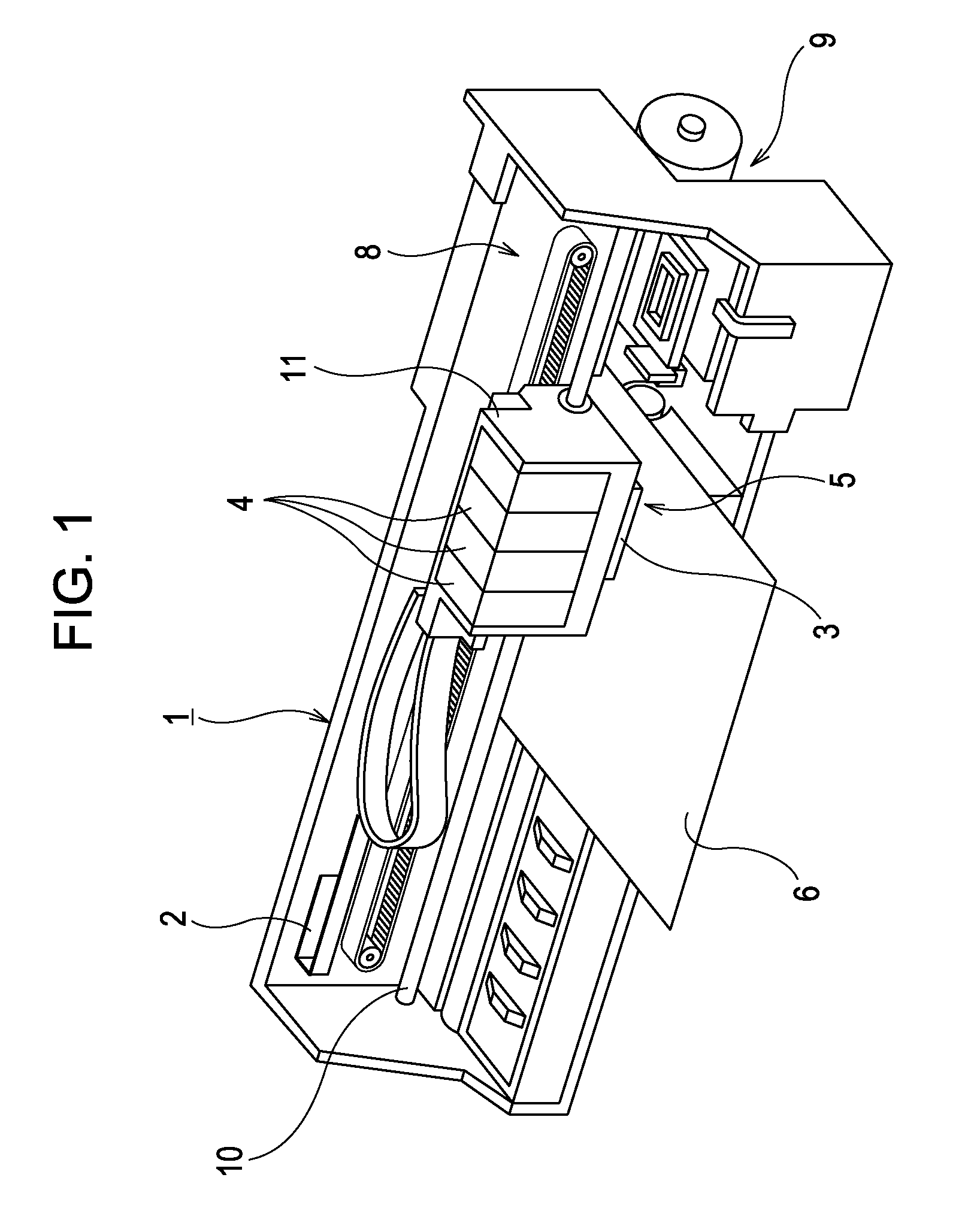
[0026]FIG. 1 is a perspective view illustrating the configuration of a printer 1. This printer 1 is generally configured of a carriage 5 in which a recording head 3 (an example of a “liquid ejecting head” according to the invention) and an ink cartridge 4 are installed, a carriage movement mechanism 8 that causes the carriage 5 (the recording head 3) to move back and forth in the paper width direction of a recording ...


PUM


Abstract

A liquid ejecting head includes nozzles that eject liquid, pressurizing chambers communicating with respective nozzles, and liquid supply channels that supply the liquid to the pressurizing chambers. The liquid ejecting head ejects the liquid when a pressure generating unit changes the pressure within the pressurizing chambers. A cylindrical nozzle straight portion, in which the opening cross-sectional area is narrower than at other areas of the nozzle, is formed toward the pressurizing chamber from the nozzle opening in each nozzle. The opening cross-sectional area of the nozzle straight portion is Sn; the length thereof is Ln; the channel cross-sectional area of the liquid supply channel is Ss; the length from a common liquid chamber-side connection opening in the liquid supply channel to a pressurizing chamber-side connection opening is Ls. The ratio (Ln / Sn) is less than or equal to ½ of the ratio (Ls / Ss).

Description

[0001]The entire disclosure of Japanese Patent Application No. 2009-226337, filed Sep. 30, 2009 is expressly incorporated by reference herein.BACKGROUND[0002]1. Technical Field[0003]The present invention relates to a liquid ejecting head such as an ink jet-type recording head and a liquid ejecting apparatus provided with such a liquid ejecting head, and particularly relates to a liquid ejecting head and a liquid ejecting apparatus capable of handling high-viscosity liquids.[0004]2. Related Art[0005]A liquid ejecting apparatus is an apparatus that includes a liquid ejecting head capable of ejecting a liquid and that ejects various types of liquid from the liquid ejecting head, causing those liquids to impact upon an impact target. An image recording apparatus such as an ink jet printer (called simply a “printer” hereinafter) that is, for example, provided with an ink jet-type recording head (an example of a liquid ejecting head; called simply a “recording head” hereinafter), and that...

Claims


Application Information

Patent Timeline
Patent Type & Authority Patents(United States)
IPC IPC(8): B41J2/14
CPCB41J2/14274B41J2002/14475B41J2202/11
Inventor OZAWA, KINYA
Owner SEIKO EPSON CORP
Why Eureka
Try Eureka