Quick install aircraft track fitting device

a technology for installing aircraft track and fittings, which is applied in the direction of machine supports, furniture parts, seating arrangements, etc., can solve the problems of traditional procedure, loose fittings in floor mounting tracks, and lock washers not being engaged with screws,

Inactive Publication Date: 2012-10-23
TIMCO AVIATION SERVICES
View PDF68 Cites 26 Cited by
  • Summary
  • Abstract
  • Description
  • Claims
  • Application Information

AI Technical Summary

Benefits of technology

[0013]A tunnel for the locking ball may extend from a forward facing outer surface of the rear section of the track fitting body into and through the vertical cylindrical piston wall. When the lever is in a lever release position, the locking ball rests both against the shoulder of the locking piston and against a tip of a locking plate carried by and extending downwardly from the lever. In this way, the locking ball is partially within the tunnel and partially against the locking piston shoulder pressing downwardly on the piston and compression spring such that the indicator flag is retracted from view. In contrast, when the lever is in the lock lever position, the locking ball rests within a detent on the locking plate allowing the compression piston spring to push the locking piston upward such that the indicator flag is visible through the indicator flag ports. It is preferred for the tunnel to extend all the way through to the outside of the track body fitting rear section, such that a small diameter tool may be inserted into the tunnel from the outside to depress the piston from its shoulder to allow the locking ball to roll back on the piston shoulder. In this way, the locking ball is free from the detent, thereby allowing the compression release spring to push forc

Problems solved by technology

One of the problems with such a traditional seat track locking device is that if the screw was not properly tightened, the lock washer may not have been engaged with the screw.
This would allow the screw to turn and loosen, which caused the fitting to become loose in the fl

Method used


Image

  • Quick install aircraft track fitting device
  • Quick install aircraft track fitting device
  • Quick install aircraft track fitting device

Examples


Embodiment Construction

[0022]In the following description, like reference characters designate like or corresponding parts throughout the several views. Also in the following description, it is to be understood that such terms as “forward,”“rearward,”“left,”“right,”“upwardly,”“downwardly,” and the like are words of convenience and are not to be construed as limiting terms.

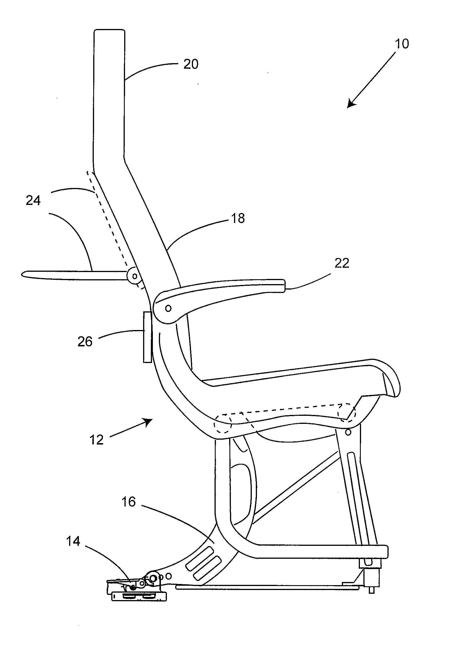
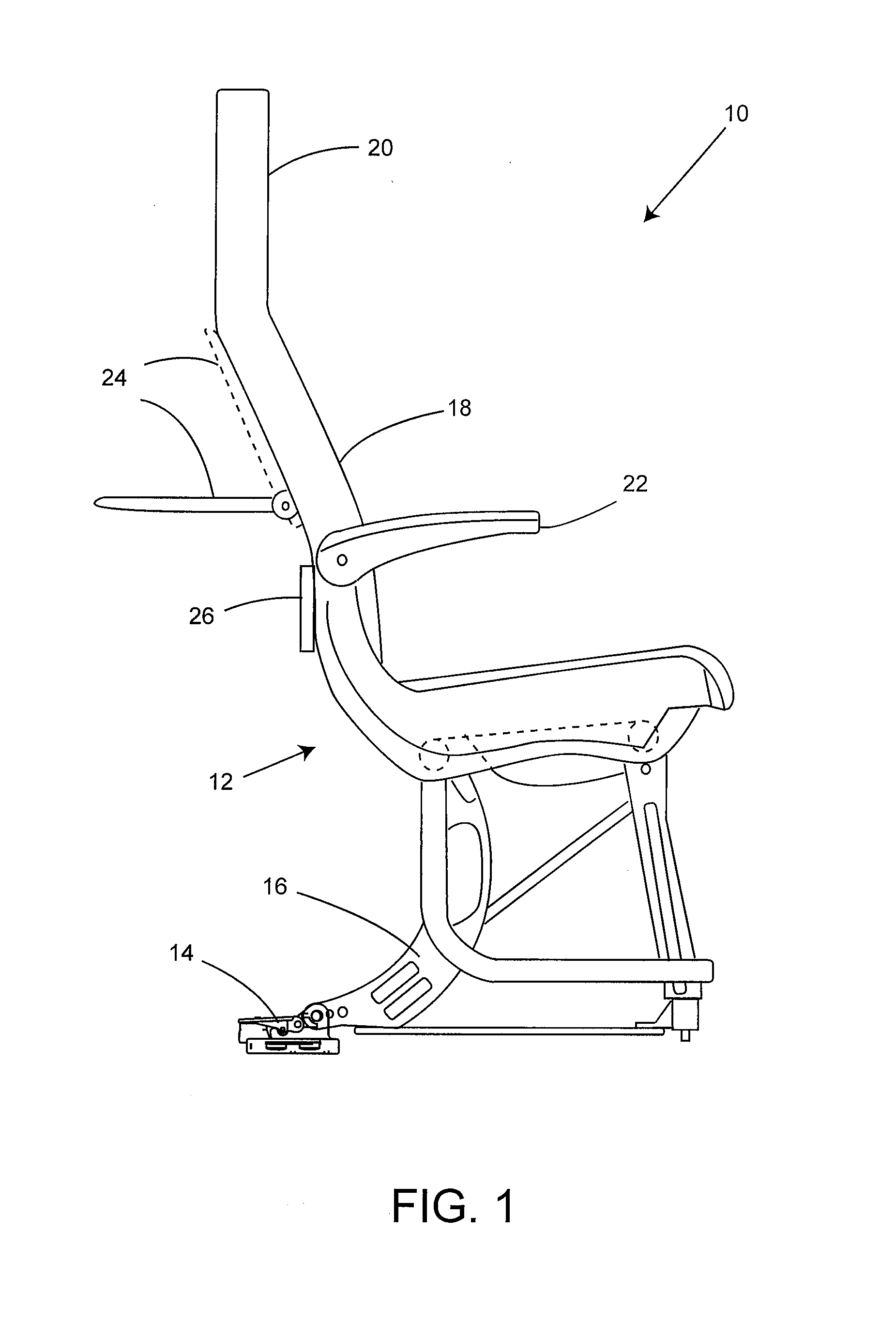
[0023]Referring now to the drawings in general and FIG. 1 in particular, the illustrations are for the purpose of describing a preferred embodiment of the inventions and are not intended to limit the inventions thereto. As best seen in FIG. 1, an improved seating apparatus for an aircraft, generally designated 10, is shown constructed according to the present invention. The improved seating apparatus 10 includes a seat assembly 12 and a quick install track fitting assembly 14 for securing the seat assembly 12 to an aircraft. The seat assembly 12 includes a seat leg 16, a seat back 18, a headrest 20, an armrest 22, a serving tray 24 and l...


PUM


Abstract

An improved seating apparatus for an aircraft includes a seat assembly and a quick install track fitting assembly for securing the seat assembly to the aircraft. In a preferred embodiment, the quick install track fitting assembly is made up of a track fitting body for insertion into an aircraft seat track and a manual lever that is pivotably attached to the track fitting body. The manual lever has a lever release position and a lever lock position. A force bearing plunger is movably attached to the manual lever for transferring force to the aircraft seat track. The force bearing plunger has a track release position and a track lock position, wherein both positions correspond to the lever release and lever lock positions of the manual lever. A lock may also be provided for maintaining the plunger in the track lock position when the manual lever is in the lever lock position. The quick install aircraft track fitting may further include a spring loaded secondary plunger to help locate and provide a secondary lock for securing the seat assembly into a proper position within the aircraft seat track. Moreover, the quick install track fitting may further include an anti-rattle feature that urges the force bearing plunger against the top of the seat track.

Description

CROSS-REFERENCES TO RELATED PATENTS AND APPLICATIONS[0001]The present application is related to, and hereby incorporates by reference in their entirety, the disclosures of the following commonly owned and assigned patents and patent applications: (i) U.S. patent application Ser. No. 12 / 273,929 filed Nov. 19, 2008 entitled “Cushion-less Aircraft Seat”; (ii) U.S. patent application Ser. No. 10 / 973,829 filed Oct. 26, 2004 and now U.S. Pat. No. 7,232,096 issued Jun. 19, 2007 entitled “Positive Lock Seat Device”; (iii) U.S. patent application Ser. No. 10 / 883,580 filed Jul. 1, 2004 and now U.S. Pat. No. 7,410,127 issued Aug. 28, 2007 entitled “Seat Track Anti-rattle Locking Device”; (iv) U.S. patent application Ser. No. 10 / 979,538 filed Nov. 2, 2004 and now U.S. Pat. No. 7,261,369 issued Aug. 28, 2007 entitled “Convertible Aircraft Passenger Seat”.BACKGROUND[0002](1) Technical Field[0003]The present inventions relate generally to an improved seating apparatus for an aircraft and, more par...

Claims


Application Information

Patent Timeline
IPC IPC(8): B64D13/00B61D45/00A47B97/00A47C1/00
CPCB64D11/0696B61D33/0057
Inventor AHAD, SAM J.ALVAREZ-TORRES, MIGUEL ANGEL
Owner TIMCO AVIATION SERVICES
Why Eureka
Try Eureka