
Bang-bang phase detector with sub-rate clock

a phase detector and sub-rate clock technology, applied in the field of clock and data recovery, can solve the problems of clock jitter and inconvenient to provide such a full rate clock

Active Publication Date: 2012-11-20
RAMBUS INC
View PDF26 Cites 67 Cited by
  • Summary
  • Abstract
  • Description
  • Claims
  • Application Information

AI Technical Summary

Problems solved by technology

Due to unavoidable signal jitter, sampling the data stream during a transition may result in capturing the value of the data bit just prior to the transition, or the value of the data bit following the transition.
As a result, the clock frequency adjustment will continue to be either to increase or to decrease with equal probability causing some clock jitter.
In receivers for very high data rates it is often inconvenient to provide such a full rate clock.

Method used


Image

  • Bang-bang phase detector with sub-rate clock
  • Bang-bang phase detector with sub-rate clock
  • Bang-bang phase detector with sub-rate clock

Examples


Embodiment Construction

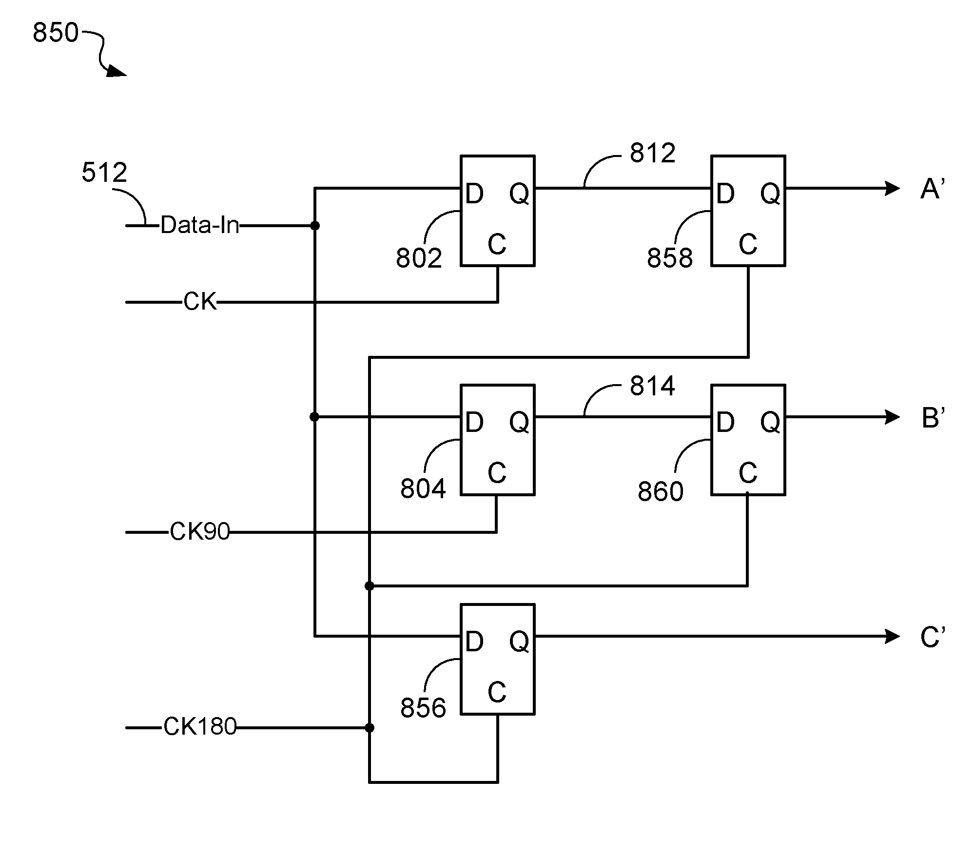
[0087]The embodiments of the present invention are concerned with a method and apparatus for implementing a bang-bang phase detector, which operates with a serial data stream and a reference clock of a reduced frequency. The reference clock frequency is reduced by at least a factor of two compared to the full rate.

[0088]FIG. 5 shows an example phase locked loop (PLL) 500 that includes a sub-rate bang-bang phase detector 502 according to an embodiment of the invention. The PLL 500 further includes an Interpretation Logic 504, a Charge Pump 506, a Loop Filter 508, and a Multi-Phase VCO 510.

[0089]The sub-rate bang-bang phase detector 502 receives an input data stream 512 and two clock signals, a reference clock (CK), and a 90° phase-shifted clock (CK90). Depending on the implementation of the bang-bang phase detector 502, a 180° phase-shifted clock (CK180) may also be used. The clock signals are generated by the Multi-Phase VCO 510. The sub-rate bang-bang phase detector 502 generates t...


PUM


Abstract

The present invention describes methods and circuitry for a sub-rate bang-bang phase detector, in which the reference clock has frequency that is a fraction of the bit rate of the received data stream. The sub-rate bang-bang phase detector is enabled by multiple phases of the reference clock.

Description

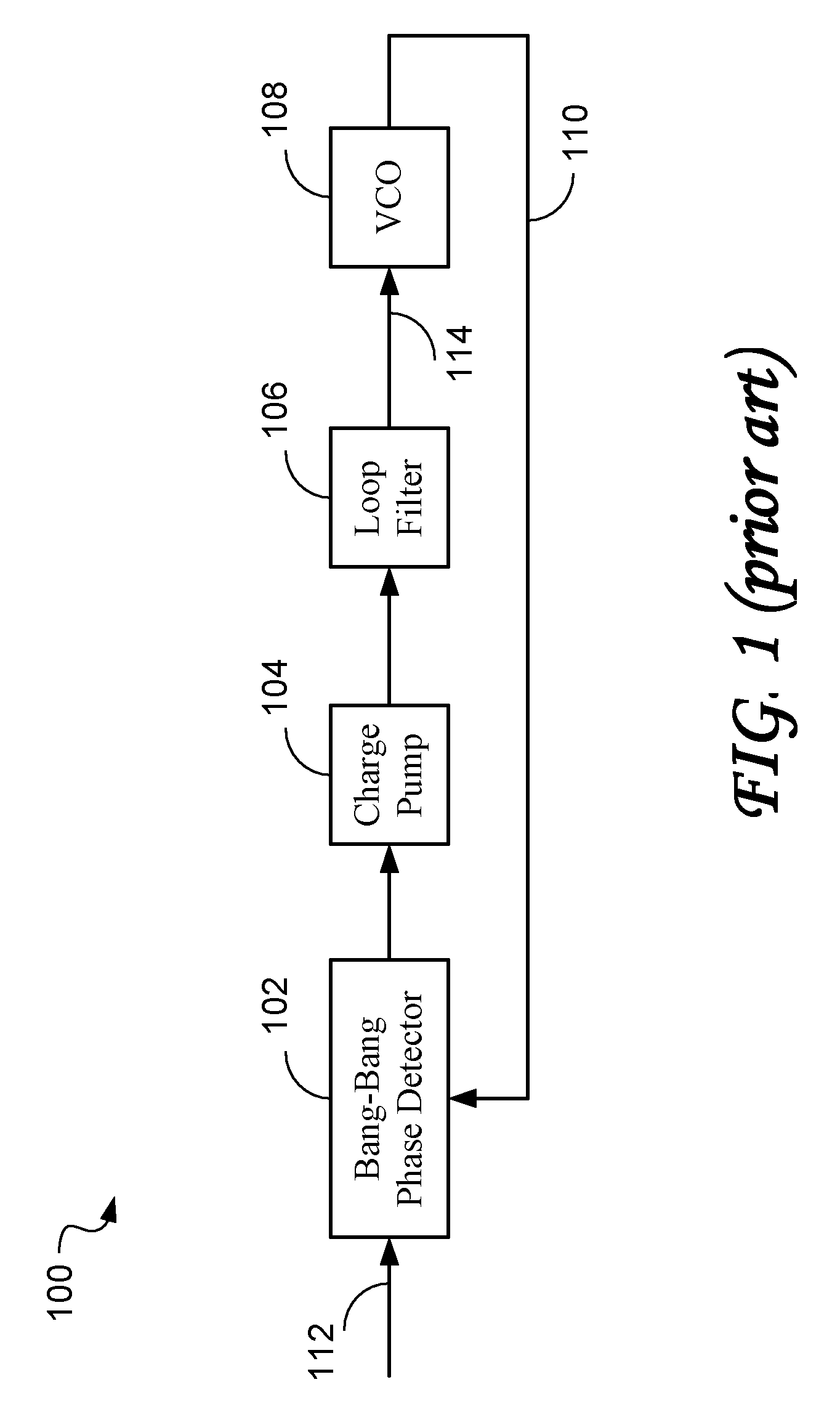
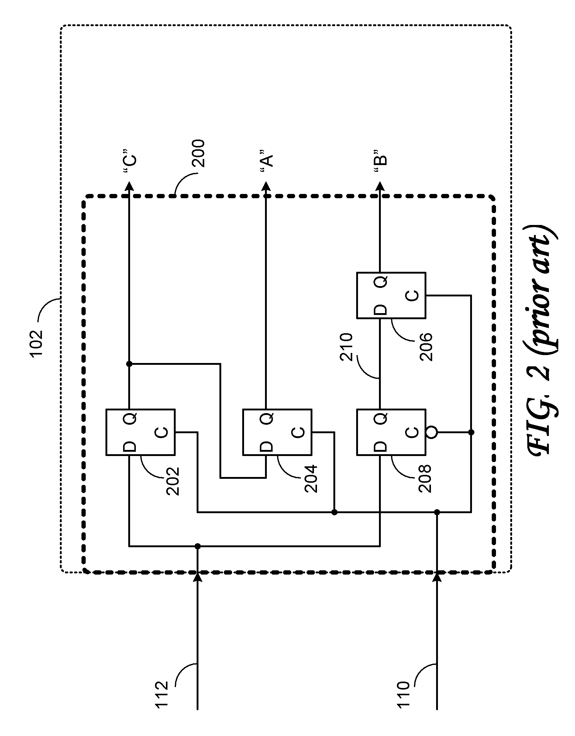
RELATED APPLICATIONS[0001]The present application claims priority from the U.S. provisional application to Badalone, Riccardo Ser. No. 61 / 001,098 filed on Oct. 31, 2007, which is incorporated herein by reference.FIELD OF THE INVENTION[0002]The present invention relates to clock and data recovery from serial data streams, phase locked loops (PLL), and specifically phase detectors for phase locked loops.BACKGROUND OF THE INVENTION[0003]Bang-bang phase detectors are commonly used as a part of a phase locked loop, in which a clock is derived from, and locked to, the transitions of a serial data signal.[0004]FIG. 1 illustrates a typical Phase locked Loop (PLL) 100 of the prior art, including a bang-bang phase detector 102, a charge pump 104, a loop filter 106, and a Voltage Controlled Oscillator (VCO) 108. The VCO 108 generates a clock signal 110 which is compared with a data signal 112 in the bang-bang phase detector 102. The output of the bang-bang phase detector 102 drives the charge ...

Claims


Application Information

Patent Timeline
Patent Type & Authority Patents(United States)
IPC IPC(8): H03D3/24
CPCH03D13/004
Inventor BADALONE, RICCARDO
Owner RAMBUS INC
Learn More