Method and system of communication employing spatial reuse reservation protocol

a technology of spatial reuse and reservation protocol, applied in the field of wireless communication, can solve the problems of substantially greater attenuation of signals broadcast or transmitted at these higher frequencies, and achieve the effects of reducing the beamwidth of the transmitting or broadcasting antenna pattern, sufficient antenna gain, and acceptable communication rang

Active Publication Date: 2012-12-04
KONINKLIJKE PHILIPS ELECTRONICS NV
View PDF3 Cites 0 Cited by
  • Summary
  • Abstract
  • Description
  • Claims
  • Application Information

AI Technical Summary

Benefits of technology

[0004]One solution to mitigate the problems of these higher frequency bands is the use of directional antennas by the wireless devices. As is well known, when the beamwidth of a transmitting or broadcasting antenna pattern is reduced, an antenna gain is achieved which has an effect as if the transmitter power level has been increased. Similarly, when the beamwidth of a receiving antenna pattern is reduced, an antenna gain is achieved which has an effect as if the received power level has been increased. By employing directional antennas with sufficiently narrow beamwidths (i.e., sufficient antenna gains) for transmission and reception, wireless devices are able to operate at higher frequency bands while still maintaining an acceptable communication range.
[0005]An additional benefit of a communication network where wireless devices use directional antennas for transmission and / or reception is spatial reuse. That is, wireless devices may point their antenna beams at different directions and transmit simultaneously without interfering with each other. For example, FIG. 1A illustrates a communication network 10 where only wireless device 12A or wireless device 12C can transmit at any given time. Otherwise, transmissions from wireless device 12A and transmissions from wireless device C will collide at devices 12B and 12D. In contrast, FIG. 1B illustrates a communication network 20 with spatial reuse. In communication network 20, device 22A can communicate with device 22D at the same time while device 22C communicates with device 22B. Compared to communication network 10 illustrated in FIG. 1A, communication network 20 illustrated in FIG. 1B—which employs spatial reuse—can double the spectral efficiency.

Problems solved by technology

Unfortunately, signals that are broadcast or transmitted at these higher frequencies suffer substantially greater attenuation—particularly when passing through intervening objects such as walls in a building—compared to signals at lower operating frequencies.

Method used


Image

  • Method and system of communication employing spatial reuse reservation protocol
  • Method and system of communication employing spatial reuse reservation protocol
  • Method and system of communication employing spatial reuse reservation protocol

Examples


Embodiment Construction

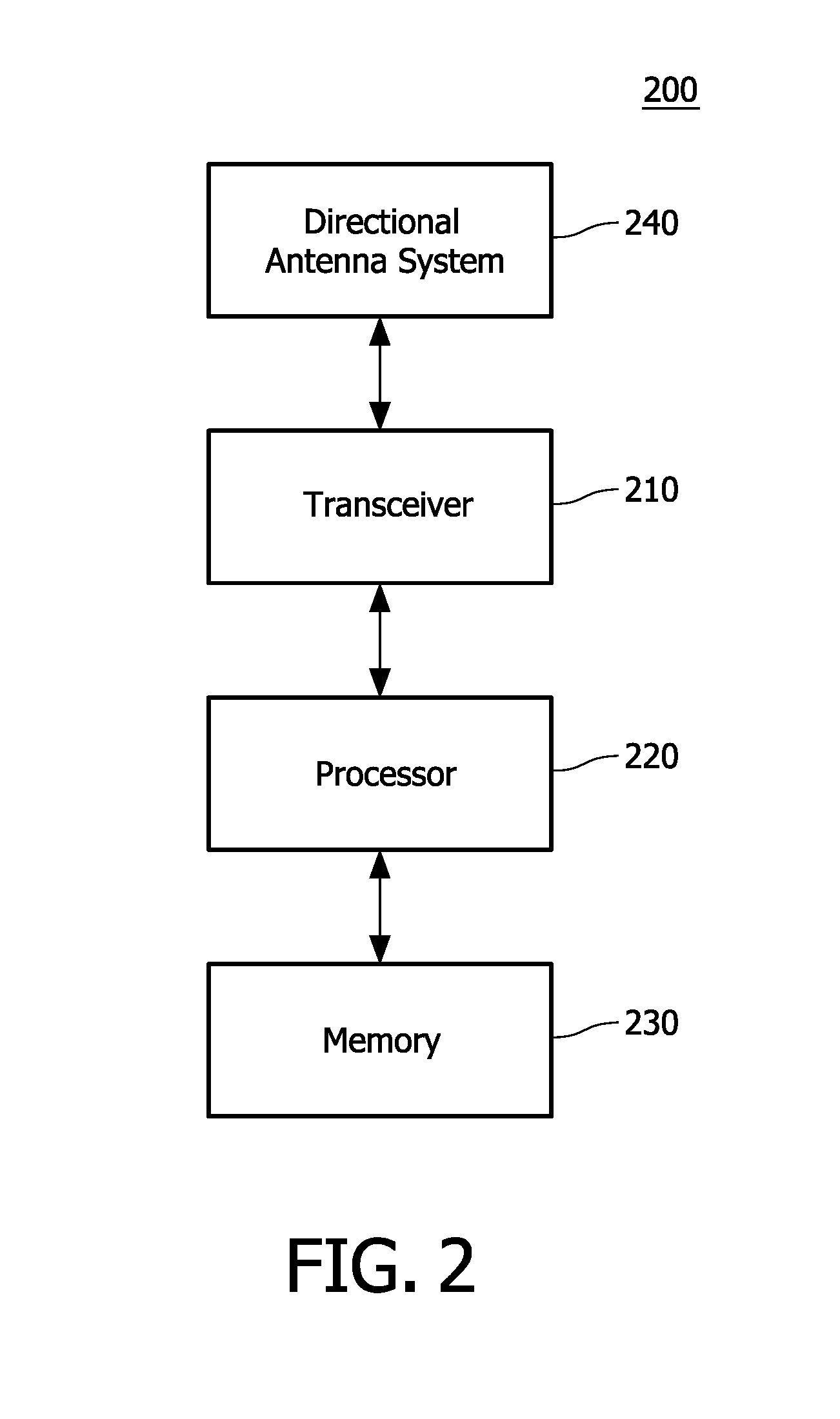
[0019]FIG. 2 is a functional block diagram of a wireless device 200. As will be appreciated by those skilled in the art, one or more of the various “parts” shown in FIG. 2 may be physically implemented using a software-controlled microprocessor, hard-wired logic circuits, or a combination thereof. Also, while the parts are functionally segregated in FIG. 2 for explanation purposes, they may be combined variously in any physical implementation.

[0020]Wireless device 200 includes a transceiver 210, processor 220, memory 230, and a directional antenna system 240.

[0021]Transceiver 210 provides functionality for wireless device 200 to communicate with other wireless devices in a communication network according to the standard protocols of the wireless network. For example, in one embodiment wireless device 200 is adapted to communicate in a communication network that operates according to IEEE 802.11.

[0022]Processor 220 is configured to execute one or more software algorithms in conjuncti...


PUM


Abstract

A wireless device (200, 310-1) executes a method (400) of reserving a time slot for communication with a second wireless device (200, 310-4) in a communication network 5 (300). The wireless device (200, 310-1) determines whether any antenna beam to be used in a proposed communication with the second wireless device (200, 310-4) communication within the time slot would interfere with any antenna beam used by any first wireless device (200, 310-i) in any existing reservations for the time slot. When any antenna beam to be used in the proposed communication would not interfere with any antenna beam used 10 by any first wireless device (200, 310-i) in any existing reservations for the time slot, the wireless device (200, 310-1) transmits an information element (500) or reserving the time slot for communication with the second wireless device (200, 310-4).

Description

CROSS-REFERENCES TO RELATED APPLICATIONS[0001]This patent application claims the priority benefit under 35 U.S.C. §119(e) of U.S. Provisional Patent Application 60 / 885,175, filed on 16 Jan. 2007, the entirety of which is hereby incorporated by reference as if fully set forth herein.TECHNICAL FIELD[0002]This invention pertains to the field of wireless communications, and more particularly to a system and method of wireless communication in a communication network that employs directional antennas.BACKGROUND AND SUMMARY[0003]In next-generation wireless communication networks, operating frequencies are in many cases much higher than in previous systems. For example, some of these networks operate at frequencies in the range of several GHz, or even higher. Unfortunately, signals that are broadcast or transmitted at these higher frequencies suffer substantially greater attenuation—particularly when passing through intervening objects such as walls in a building—compared to signals at low...

Claims


Application Information

Patent Timeline
Patent Type & Authority Patents(United States)
IPC IPC(8): H04L12/56H04J1/16H04L47/724H04W72/02
CPCH04W72/02H04W28/26H04W72/082H04W72/541H04B7/02
Inventor CHOU, CHUN-TING
Owner KONINKLIJKE PHILIPS ELECTRONICS NV
Why Eureka
Try Eureka