Expanding vertebral body implant

a technology of expanding vertebrae and implants, which is applied in the field of expanding vertebrae with medical implants, can solve the problems of all or part of more than one vertebrae being damaged, one or more vertebrae becoming damaged, and affecting so as to increase the overall height of the implan

Active Publication Date: 2012-12-11
WARSAW ORTHOPEDIC INC
View PDF98 Cites 19 Cited by
  • Summary
  • Abstract
  • Description
  • Claims
  • Application Information

AI Technical Summary

Benefits of technology

[0005]In one exemplary aspect, an expandable medical implant for supporting bone structures is disclosed. The implant has an overall implant height adjustable along a longitudinal axis. The implant may include an outer member configured to cooperatively engage a first bone structure and an inner member receivable in the outer member. The inner member may be movable relative to the outer member to increase and decrease the overall implant height. The inner member may be configured to cooperatively engage a second bone structure. One of the outer and inner members includes a tapered surface and the other of the outer and inner members includes a scalloped surface. The implant may also include a locking element disposed between the tapered surface and the scalloped surface. The tapered surface may be movable relative to the locking element to transversely shift the locking element into engagement with the scalloped surface to inhibit a decrease in the overall implant height.

Problems solved by technology

For example, one or more of the vertebrae may become damaged as a result of tumor growth, or may become damaged by a traumatic or other event.
All or part of more than one vertebrae may be damaged and require removal and replacement in some circumstances.

Method used


Image

  • Expanding vertebral body implant
  • Expanding vertebral body implant
  • Expanding vertebral body implant

Examples


Embodiment Construction

[0029]For the purposes of promoting an understanding of the principles of the invention, reference will now be made to the embodiments, or examples, illustrated in the drawings and specific language will be used to describe the same. It will nevertheless be understood that no limitation of the scope of the invention is thereby intended. Any alterations and further modifications in the described embodiments, and any further applications of the principles of the invention as described herein are contemplated as would normally occur to one skilled in the art to which the invention relates.

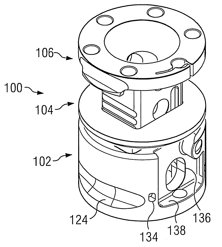
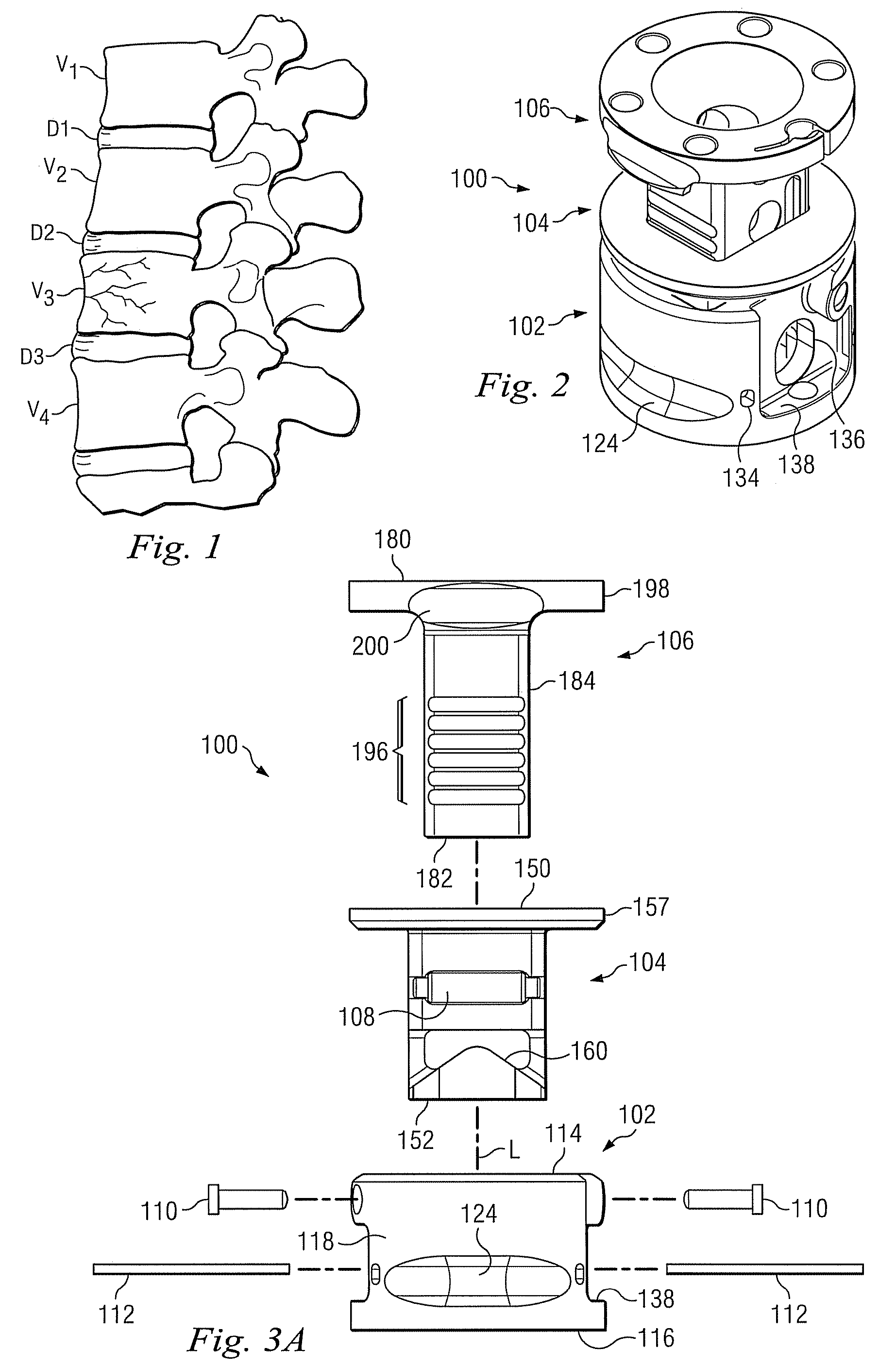
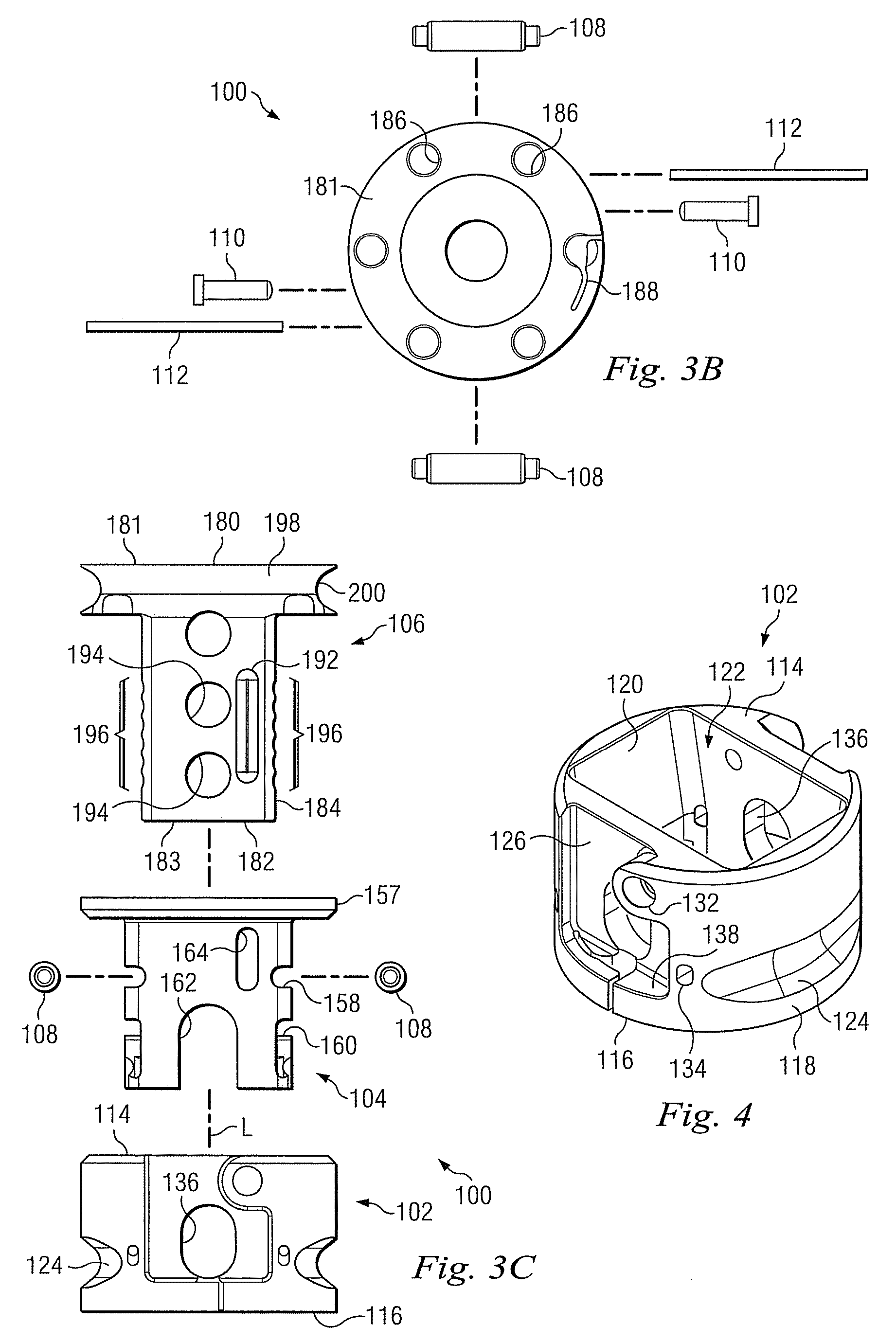
[0030]FIGS. 2 and 3a-3c show an exemplary expandable implant 100 usable to secure and space adjacent bone structures. In FIG. 2, the implant 100 is shown fully assembled, while FIGS. 3a-3c show the implant 100 in an exploded condition, along a longitudinal axis L. Referring to these figures, the implant 100 includes three main components, including a base 102, a locker 104, and a post 106. These main ...


PUM


Abstract

An expandable medical implant for supporting bone structures is disclosed. The implant may include an outer member and an inner member receivable in the outer member. One of the outer and inner members includes a tapered surface and the other of the outer and inner members includes a scalloped surface. The implant may also include a locking element disposed between the tapered surface and the scalloped surface. The tapered surface may be movable relative to the locking element to transversely shift the locking element into engagement with the scalloped surface to inhibit a decrease in the overall implant height.

Description

FIELD OF THE INVENTION[0001]The present invention relates generally to the field of replacing portions of the human structural anatomy with medical implants, and more particularly relates to an expandable implant and method for replacing bone structures such as one or more vertebrae or long bones.BACKGROUND[0002]It is sometimes necessary to remove one or more vertebrae, or a portion of the vertebrae, from the human spine in response to various pathologies. For example, one or more of the vertebrae may become damaged as a result of tumor growth, or may become damaged by a traumatic or other event. Excision of at least a generally anterior portion, or vertebral body, of the vertebra may be referred to as a corpectomy. An implant is usually placed between the remaining vertebrae to provide structural support for the spine as a part of a corpectomy. FIG. 1 illustrates four vertebrae, V1-V4 of a typical lumbar spine and three spinal discs, D1-D3. As illustrated, V3 is a damaged vertebra ...

Claims


Application Information

Patent Timeline
Patent Type & Authority Patents(United States)
IPC IPC(8): A61F2/44
CPCA61F2/44A61F2/30965A61F2/4611A61F2002/2835A61F2002/30153A61F2002/30154A61F2002/30224A61F2002/30235A61F2002/30377A61F2002/30492A61F2002/30505A61F2002/3055A61F2002/30551A61F2002/30601A61F2002/30785A61F2002/30787A61F2002/30828A61F2002/4475A61F2220/0025A61F2220/0033A61F2230/0019A61F2230/0021A61F2230/0069A61F2002/30367A61F2002/30593
Inventor CAPOTE, MARCO D.MILLER, KEITH E.KARAHALIOS, DEAN G.POTTS, ERIC A.
Owner WARSAW ORTHOPEDIC INC
Why Eureka
Try Eureka